
Station Defined Frames#
Warning
This tutorial is new ⭐, and StationDefinedFrame s require OpenSim >= v4.5.1. The content
of this tutorial should be valid long-term, but we are waiting for OpenSim GUI v4.6 to be
released before we remove any “experimental” labelling. We also anticipate adding some handy
tooling around re-socketing existing joints and defining StationDefinedFrame s.
This tutorial focuses on the StationDefinedFrame component, which was
merged into OpenSim in opensim-core/pull/3694 and should be available in
OpenSim >= v4.5.1. Specifically, this tutorial focuses on adding
StationDefinedFrames via OpenSim Creator. If you’re more interested
in the underlying implementation, or its associated OpenSim API,
then StationDefinedFrame.h provides a technical (C++) description.
Overview#
Frames are defined to compose a right-handed set of three orthogonal axes (an
orientation) and an origin point (a translation). OpenSim has a Frame abstraction
that it uses when defining almost all spatial relationships. Joints
join Frames bodies are a Frame ; muscle path points are defined within
Frames (as are markers); and meshes, contact geometry, and wrap surfaces are
attached to (and defined in) Frames.
A Frame ‘s transform can be constant (e.g. Ground), based on constraints (e.g. Body),
or user-defined (e.g. PhysicalOffsetFrame). User-defined Frame s are the primary
way that modellers define spatial relationships in an OpenSim model.
PhysicalOffsetFrame Example
An OpenSim model might contain a PinJoint definition that attaches to
a PhysicalOffsetFrame in order to customize the joint center. The offset frame’s
osim XML may look something like this:
<PhysicalOffsetFrame name="body_offset">
    <socket_parent>/bodyset/some_body</socket_parent>
    <translation>0 0.8 0</translation>
    <orientation>1.5707 0 0</orientation>
</PhysicalOffsetFrame>
Where socket_parent indicates which frame body_offset is defined in,
translation defines its translation within the parent (here, some_body),
and orientation defines its orientation with respect to that
parent. OpenSim uses this information like this at runtime to figure out
where (e.g.) bodies and muscle points are.
StationDefinedFrame s are user-defined Frame s that derive their transform
from relationships between stations (body-fixed points) in the model. This more
closely mirrors how anatomical joint/body frames are formally defined
(e.g. Grood et. al., Wu et. al.). It’s also compatible with algorithms
that operate on points (e.g. TPS warping, see The Mesh Warper). The
mathematical relationship between stations in the model and the StationDefinedFrame
are shown in Fig. 66.

Fig. 66 The relationship between stations and a StationDefinedFrame. \(\mathbf{a}\),
\(\mathbf{b}\), \(\mathbf{c}\), and \(\mathbf{o}\) (origin) are four
stations in the model that must be attached—either directly, or indirectly (e.g.
via a PhysicalOffsetFrame)—to the same body. The StationDefinedFrame
implementation uses the stations to derive \(f(\mathbf{v})\), its transform
function. The origin station, \(\mathbf{o}\), may be coincident with one of
the other stations.#
Practically speaking, this means is that StationDefinedFrame s let modellers
define frames by choosing/calculating 3 or 4 stations (landmarks) on each body. Once
that relationship is established, the resulting frame is automatically recalculated
whenever the the stations moved (e.g. due to scaling, warping, shear, etc.).
Example Walkthrough#
OpenSim Creator includes example models that use StationDefinedFrame:
StationDefinedFrameExample.osim: A simple example that contains four stations defined in one body with aStationDefinedFramethat’s defined by the stations.StationDefinedFrameAdvancedExample.osim: A more advanced example that contains multipleStationDefinedFrames that are chained and use stations attached viaPhysicalOffsetFrames.
This walkthrough outlines creating something similar to StationDefinedFrame.osim, so
that you can get an idea of how the mathematics (Fig. 66) is exposed via
OpenSim’s component system.
Make a One-Body Model#
Create a blank OpenSim model (e.g. from the splash screen or main menu).
Add a body to the model (as described in Add a Body with a WeldJoint), attach a brick geometry to the body, so it’s easier to visualize.
You should end up with something like Fig. 67.
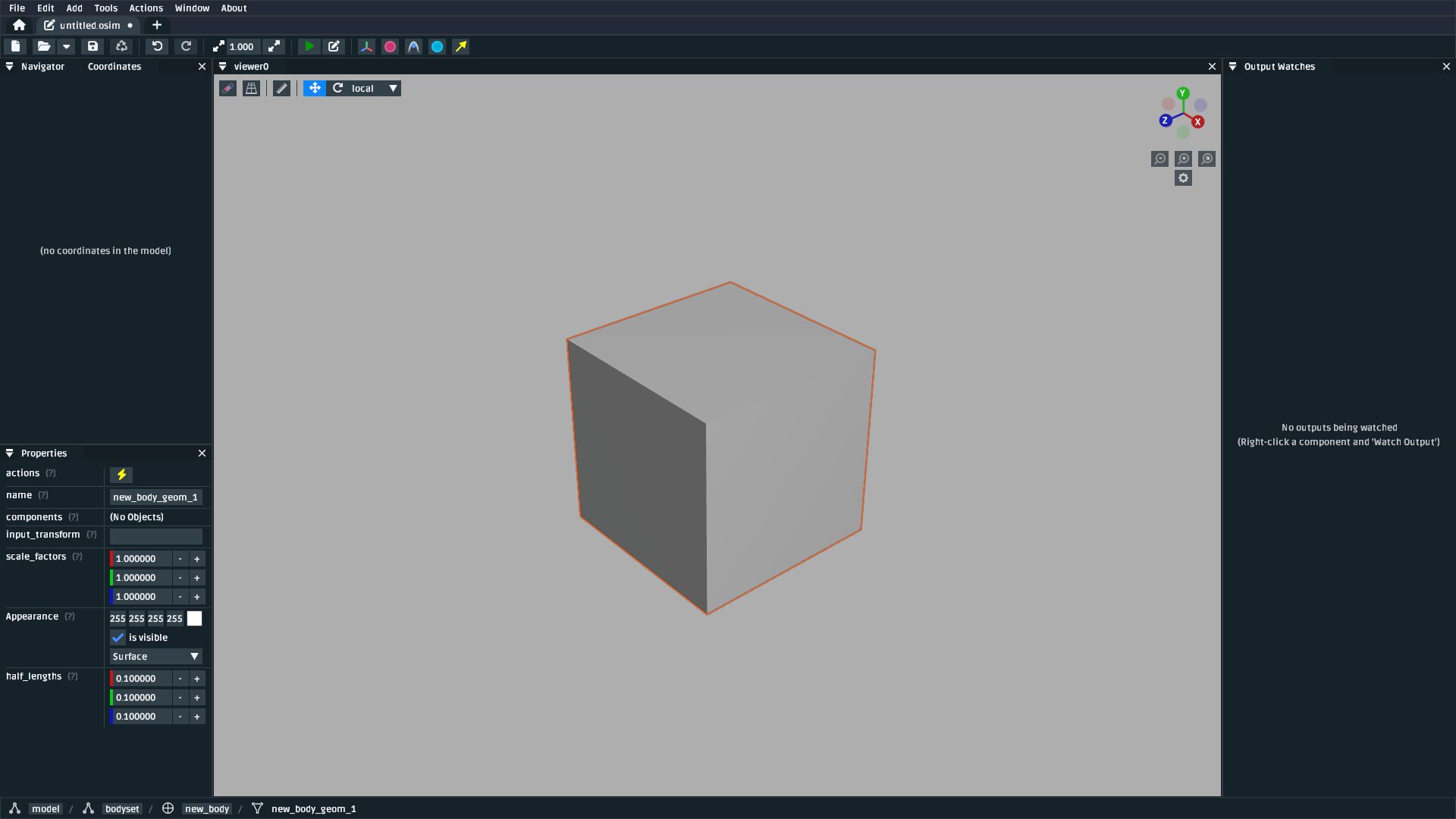
Fig. 67 A model containing one body with a brick geometry attached to it.#
Add Stations to the Body#
With a body defined, we now need to define four stations in the body. Mathematically, each of these stations is equivalent to the \(\mathbf{a}\), \(\mathbf{b}\), \(\mathbf{c}\), and \(\mathbf{o}\) point vectors in Fig. 66. Repeat the following process four times:
Open the
Addcontext menu by right-clicking somewhere in a 3D visualizer. Add aStationby finding it in this menu (Component>Station). This will bring up a dialog that looks like Fig. 68 through which you can add aStationcomponent.
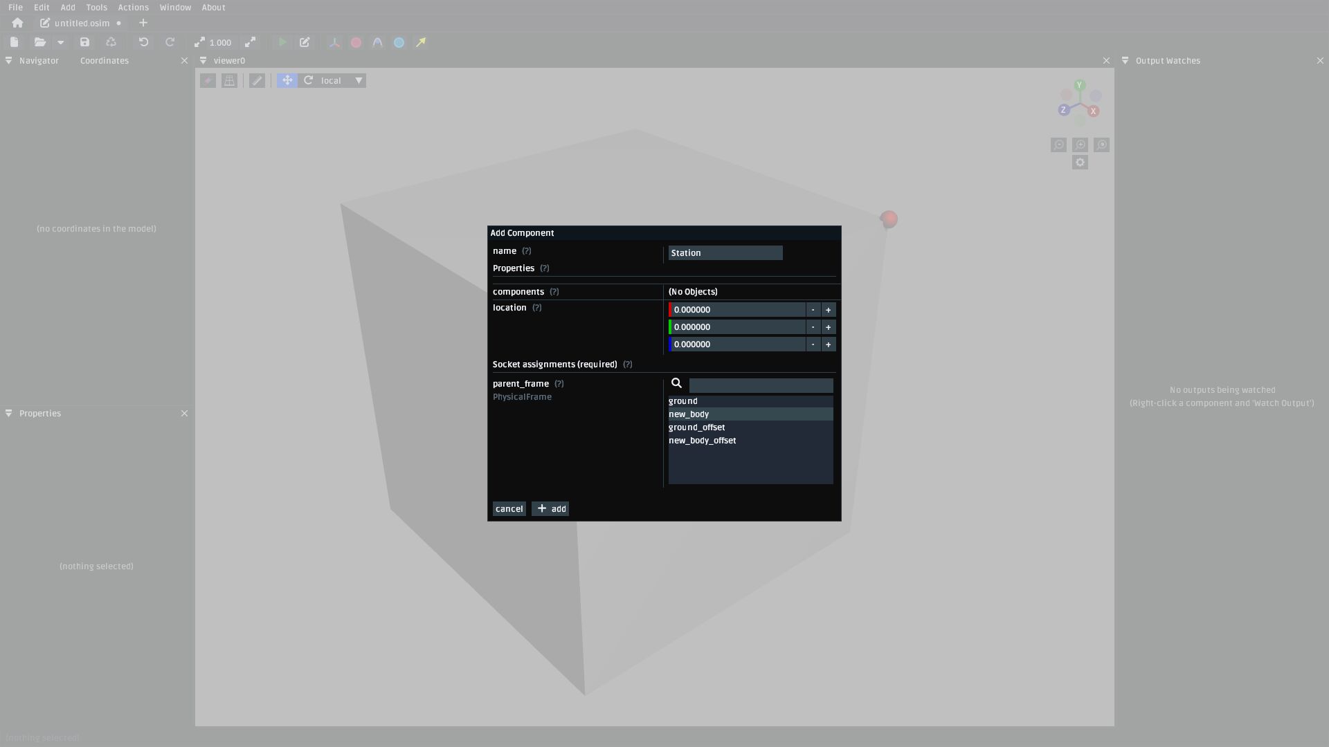
Fig. 68 The add Station dialog. Use this to attach four stations to the body by choosing the body as
the parent_frame.#
2. Place the four stations somewhere in the model. An example is shown in Fig. 69. In it, all the stations were placed on the brick face and the origin station (\(\mathbf{o}\)) was placed in the center.
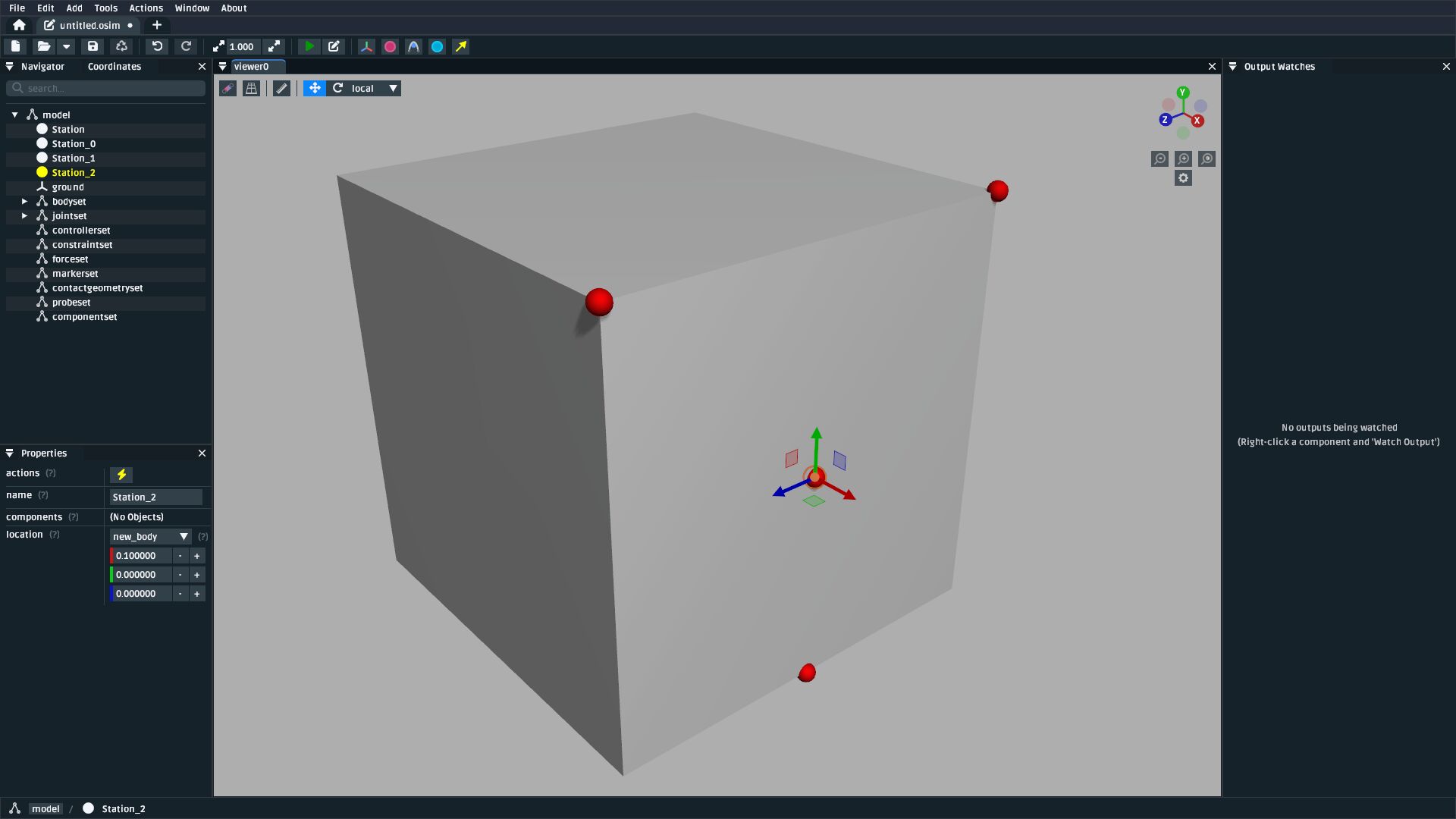
Fig. 69 The model after placing four stations attached to the body.#
Add a StationDefinedFrame#
Note
StationDefinedFrame is currently placed in the Experimental Components section because, although
it’s supported/merged into upstream OpenSim, it’s only supported in versions >= v4.5.1. At time of
writing (2025/05/15), the latest available version of OpenSim GUI is v4.5.0, which doesn’t
support StationDefinedFrame s yet 😞.
Open the
Addcontext menu by right-clicking somewhere in a 3D visualizer. Add aStationDefinedFrameby finding it in this menu (Experimental Components>StationDefinedFrame). This will bring up a dialog that looks like Fig. 70 through which you can add aStationDefinedFramecomponent.Make sure to select the correct
Stations forpoint_a,point_b, etc.
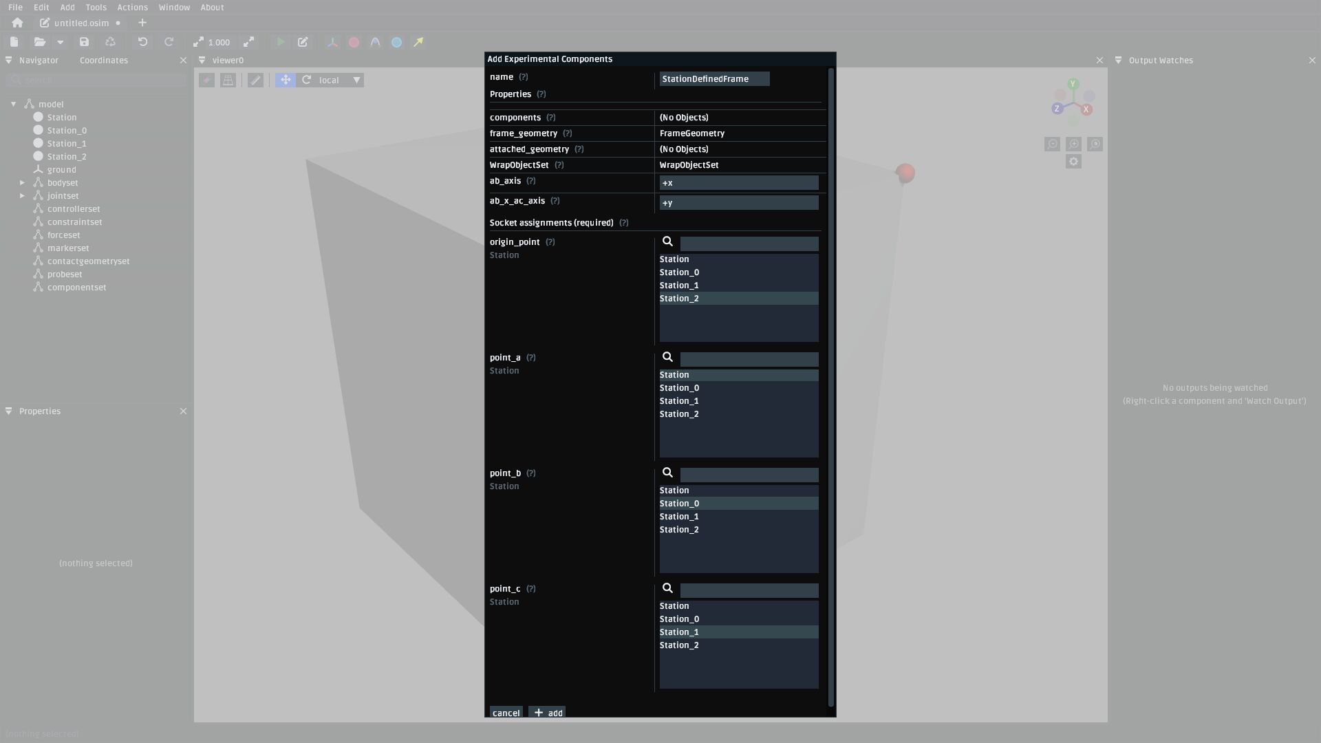
Fig. 70 The add StationDefinedFrame dialog. The ab_axis property is used to customize
which joint axis the \(\mathbf{\hat{e}_1}\) axis (Fig. 66) maps onto when the implementation
ultimately calculates the frame’s rotation (\(\mathbf{R}\), in Fig. 66).
The ab_x_ac_axis is used to customize which axis the cross product maps
onto (\(\hat{\mathbf{e_3}}\) in Fig. 66). You don’t need to use
either ab_axis or ab_x_ac_axis yet, but just be aware that they are available
if you want to flip/change an axis later on.#
After adding the
StationDefinedFrameto the model, you should be able to see it in the visualizer (Fig. 71)
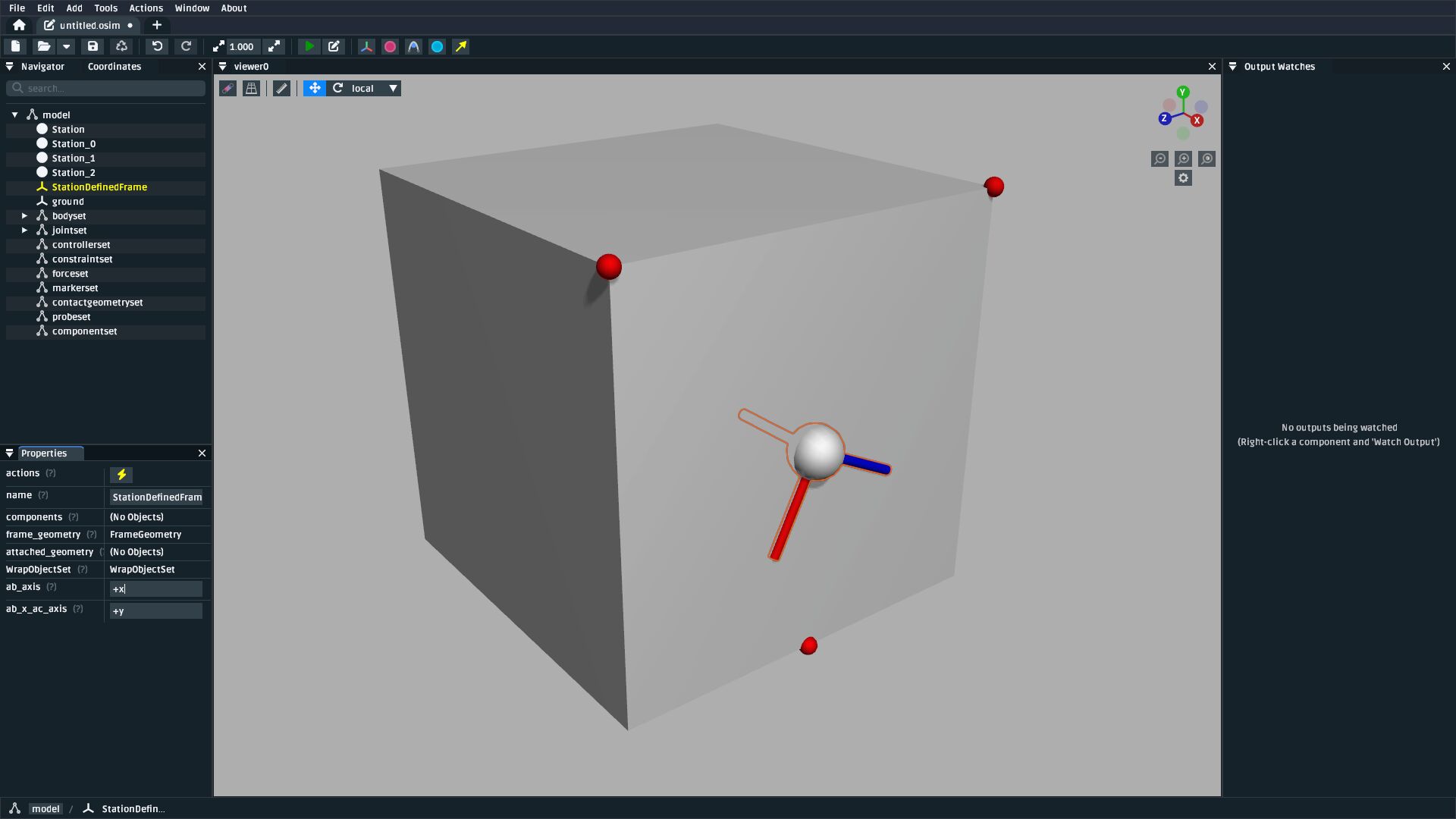
Fig. 71 The model after adding a StationDefinedFrame. The frame’s location and orientation is
entirely derived from the Station s, which more closely mimics how frames are defined
in biomechanical systems.#
The resulting StationDefinedFrame can be used with anything in OpenSim that depends on a
Frame, such as joints, geometry, stations, offset frames, and so on.
In principle, you could have used a PhysicalOffsetFrame to produce a frame with the same
orientation and translation as this StationDefinedFrame, but doing that would
require manually calculating the origin and rotation. It also wouldn’t automatically recalculate
those quantities when the model is scaled non-linearly (e.g. with the Thin-Plate Spline
technique, as described in The Mesh Warper).
Join Something to the StationDefinedFrame#
The most common use for a StationDefinedFrame is to use it in a joint definition, because
that’s an important part of designing models. There’s two ways to do this, outlined below.
Using a StationDefinedFrame as a Parent Frame When Adding a New Body#
When adding a body to a model (e.g. as described in Add a Body with a WeldJoint) a
joint is also added (the body has to join to something, as far as OpenSim is
concerned) and you can select the added StationDefinedFrame as what it joins to
directly in the add body dialog (Fig. 72).
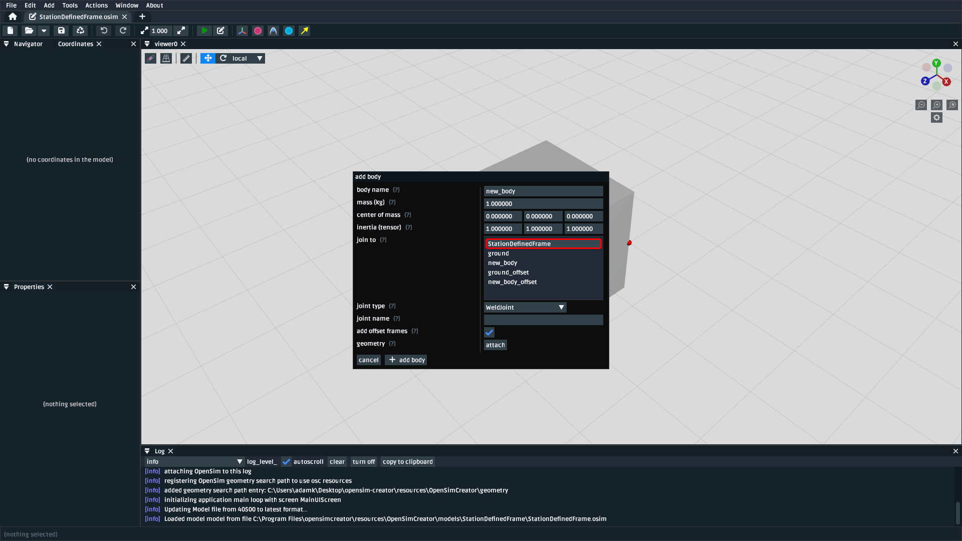
Fig. 72 When adding a new body, you can select a StationDefinedFrame that’s already in
the model as the parent frame for the body’s joint.#
Once you have added the new body this way, you might want to then define a
StationDefinedFrame on the new body. That’s fine: the procedure for adding
the new StationDefinedFrame is identical to the start of this walkthrough. After
you have a StationDefinedFrame defined on the new body, you can then use the
procedure below to modify a joint to use that frame.
Using a StationDefinedFrame as a Parent/Child Frame in an Existing Joint#
Joints in OpenSim models work by coupling two frames that are referenced via sockets
(named parent_frame and child_frame) on the joint. Therefore, assuming you have
a StationDefinedFrame in your model, you can follow this procedure to modify an
existing joint to use it:
Identify which joint you want to re-socket (e.g. in the navigator panel).
Right-click the joint and use the
Socketsmenu to change either the joint’sparent_frameorchild_framesockets to point to yourStationDefinedFrame(Fig. 73).The joint will now use the
StationDefinedFrameas one of the two frames it connects.
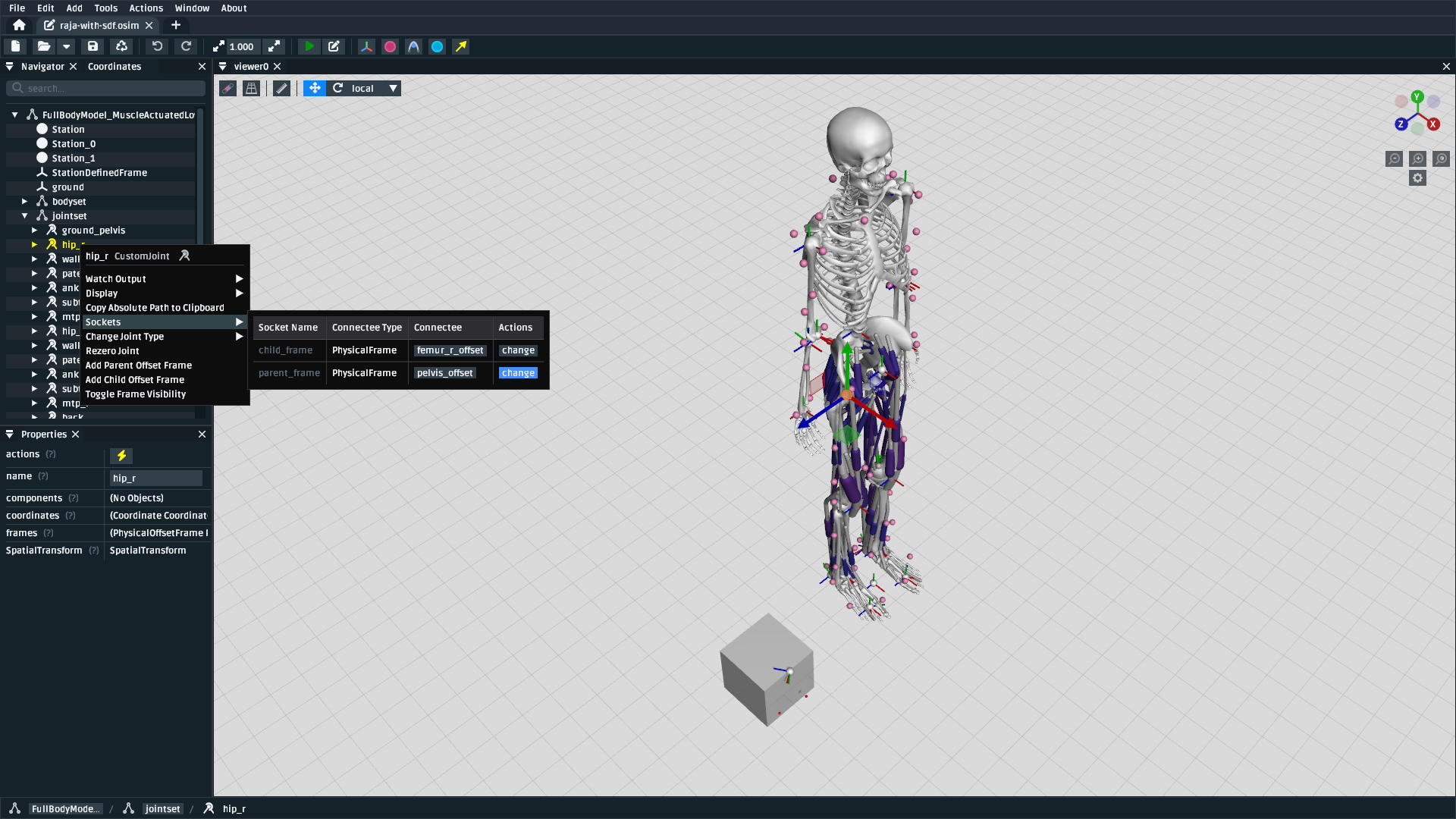
Fig. 73 The frames that joints connect in an OpenSim model can be edited via the
Sockets context menu.#
Warning
Changing the child_frame socket has pitfalls.
Because the StationDefinedFrame is usually defined within a body, and that body
is likely already joined to ground either directly or indirectly, you can end up
creating kinematic cycle that the OpenSim engine will try to satisfy, but can’t, producing
and error message in the log.
Unfortunately, the solution to this problem requires performing two model mutations in one step:
Delete the (temporary) joint between the
StationDefinedFrame‘s body and ground (if feasible).Attach the existing joint to the
StationDefinedFrame.
OpenSim Creator can’t automatically figure out how to do this for all model types (it doesn’t know
what you want), so may have to manually go into the osim file’s XML and delete
the joint followed by pointing the existing joint’s <child_frame> at your
StationDefinedFrame.