
The Model Warper#
Warning
The model warper is very very 🪄 experimental 🪄.
The model warper has been in development since 2023 and has undergone several redesigns from its initial version (an extended form of The Mesh Warper) to what it is now. This is because because non-linear “model warping” combines a variety of scaling algorithms in a model-specific way - our goal is to provide clear UI tooling that makes combining various scaling algorithms into a single pipeline easier.
We invite you to try the model warper out and get a feel for how it might be useful. Maybe it’s already useful enough for you to use it in something serious.
In this tutorial, we will be using the model warper to create a warping pipeline that can be used to warp an entire OpenSim model using subject-specific data, such as CT scans and weight measurements. The benefit of the model warper is that it lets you combine various, potentially non-uniform, scaling steps into a single warping pipeline that’s standard, introspectible, and reusable.
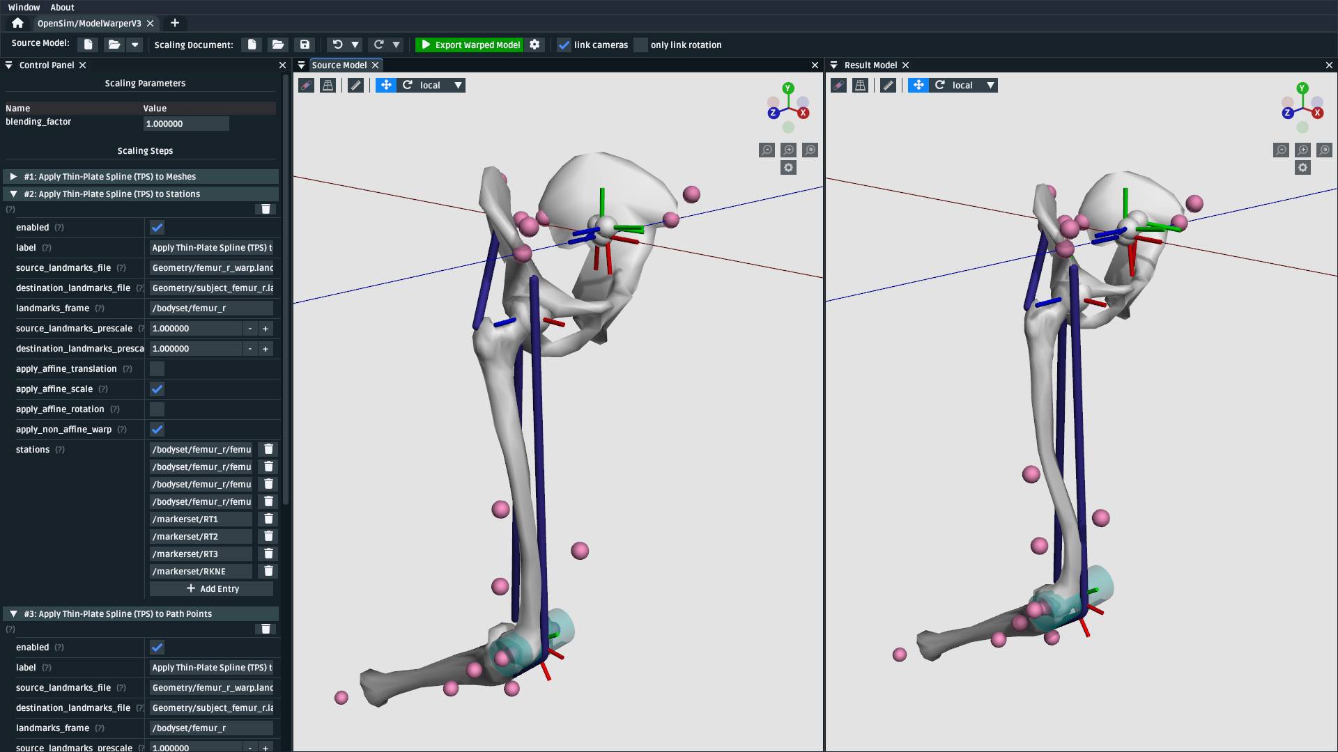
Fig. 106 The model warping UI. This tutorial goes through top-level model warping concepts and how OpenSim Creator’s UI tooling helps design and execute a model warping procedure.#
Prerequisites#
You can diagnose and work with OpenSim models. This tutorial assumes that you’re able to diagnose the models that go into, and come out of, the model warping UI. If you don’t feel comfortable with working on OpenSim models, then we recommend going through some model-building tutorials (e.g. Make a Pendulum, Make a Bouncing Block).
A basic understanding of the Thin-Plate Spline (TPS) technique. The walkthrough in this tutorial uses the TPS technique to warp parts of the model. Therefore, it’s recommended that you have already gone through The Mesh Warper, which outlines pairing landmarks between two corresponding meshes as inputs for the TPS technique.
Familiarity with StationDefinedFrames. The walkthrough in this tutorial uses a model that contains
StationDefinedFrames so that non-linear TPS scaling steps correctly recompute the model’s joint frames. The Station Defined Frames documentation outlines whatStationDefinedFrames are and how to add them to models.Familiarity with the previous tutorial: The model created in Make a Leg is the source model in this one, so going through it will provide valuable context about the source model’s design.
Topics Covered by this Tutorial#
A technical overview of how the model warper works
A concrete walkthrough of warping the model from Make a Leg
An explanation of how model warping behavior can be customized
Technical Overview#
A model warping procedure applies a sequence of scaling steps to the source model one-at-a-time to yield a result model. Each scaling step may require some sort of scaling parameter, or external data, to execute successfully. Model warping procedures are customizable. The number, order, and behavior of each scaling step may differ from procedure to procedure. This is to accomodate a variety of source models, experiments, and scaling requirements.
OpenSim Creator provides a workflow for designing and executing a model warping procedure, pictured in Fig. 107. The workflow UI is designed to provide visual feedback about each scaling step, so that you can incrementally build a warping procedure one scaling step at a time. The model warping procedure (scaling document) can then be saved to a standard XML file so that it can be reused and modified.
Fig. 107 The model warping workflow UI contains a toolbar with buttons for creating/loading the source model, warping procedure, and various other useful functions (top); a control panel for editing the scaling parameters of a warping procedure and an editable list of toggleable scaling steps which are applied in-order (left); and 3D views that show the source model and result (warped) model after applying the scaling steps side-by-side (right).#
Walkthrough#
This walkthrough goes through the process of building a model warping procedure for the model made in Make a Leg from scratch. The aim is to show how the model warping workflow can be used to build a multi-step model warping pipeline containing non-linear scaling steps.
The warping procedure we design here will try to account for femoral torsion in the subject. Torsion is tricky to handle because standard scaling techniques, which typically perform linear scaling, cannot account for localized, morpological changes.
Open the Model Warper Workflow UI#
The model warper is a specialized workflow in OpenSim Creator and can be accessed from the splash screen:
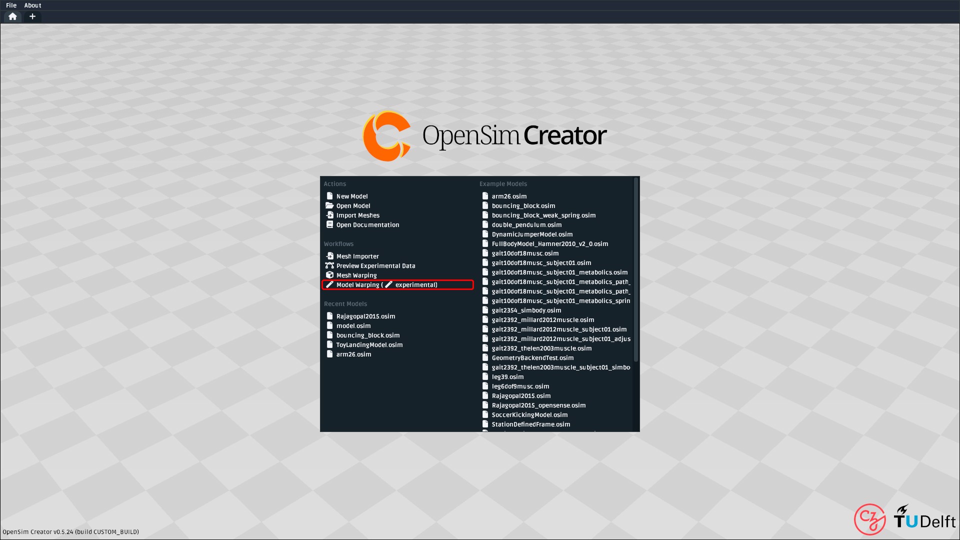
Fig. 108 The model warper can be opened from the splash screen of OpenSim Creator (circled red).#
This should open a blank model that has no scaling steps:
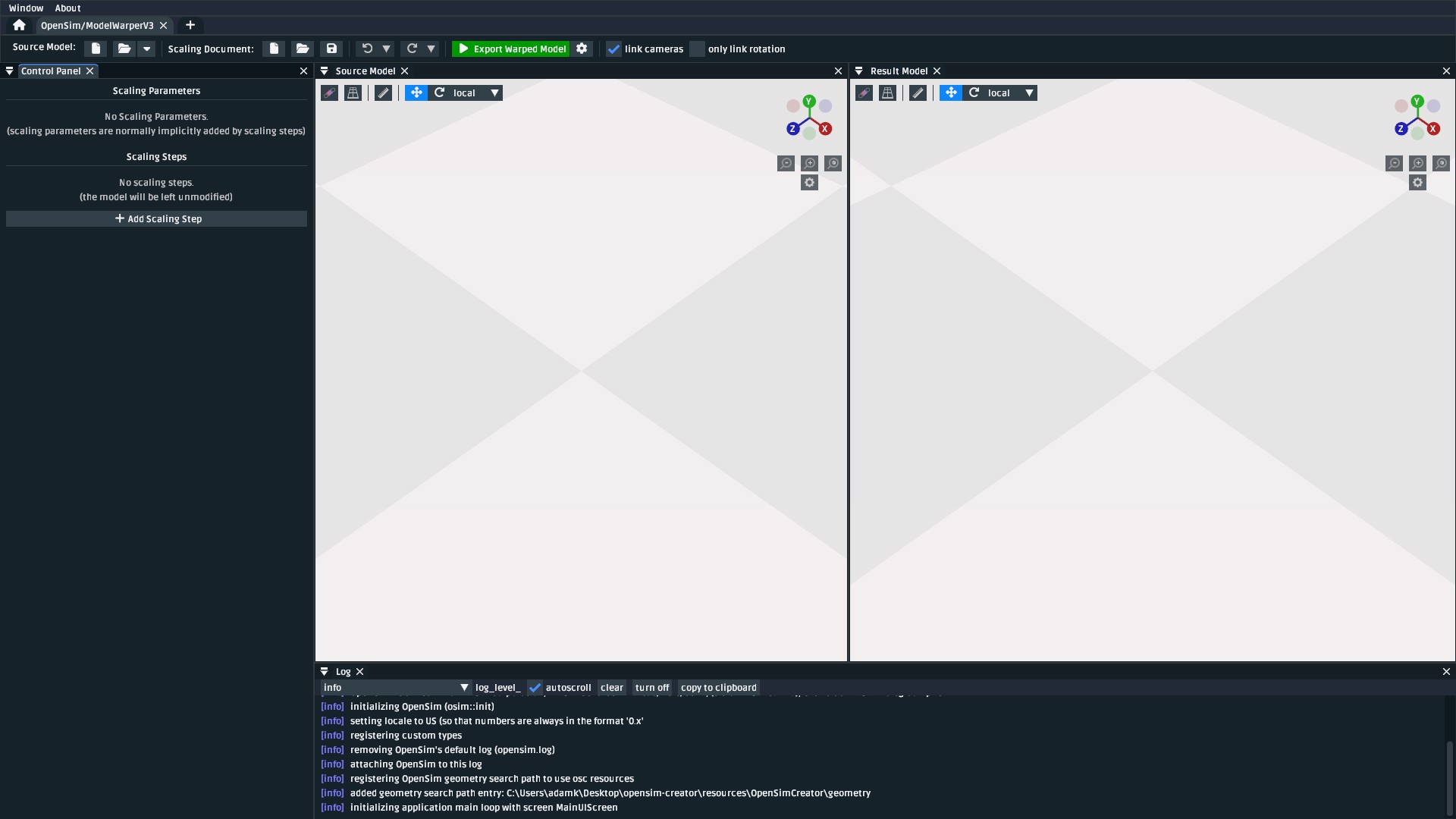
Fig. 109 A screenshot of the model warping UI when it’s first opened.#
Load the Source Model#
Note
The source model for this workflow is the final (cleaned up) model made in Make a Leg. You
can access it by downloading Walkthrough Model ZIP, which contains the final model built in
that tutorial, named make-a-leg_final.osim.
Briefly, if you’re unfamiliar with the model:
It contains three bodies (
pelvis,femur_r, andtibia_r).Joints at the hip (
hip_r, aBallJoint) and knee (knee_r, aPinJoint).Three muscles (
glmed_r,semimem_r, andrecfem_r).One of the muscles (
recfem_r) wraps over aWrapCylinderat the knee.All joint frames in the model are
StationDefinedFrames, which means they can be recalculated by warping their associatedStations (crucial).
Use the Source Model entry in the model warper’s toolbar to load make-a-leg_final.osim
as the source model. This should load the model and show it in the Source Model UI panel:
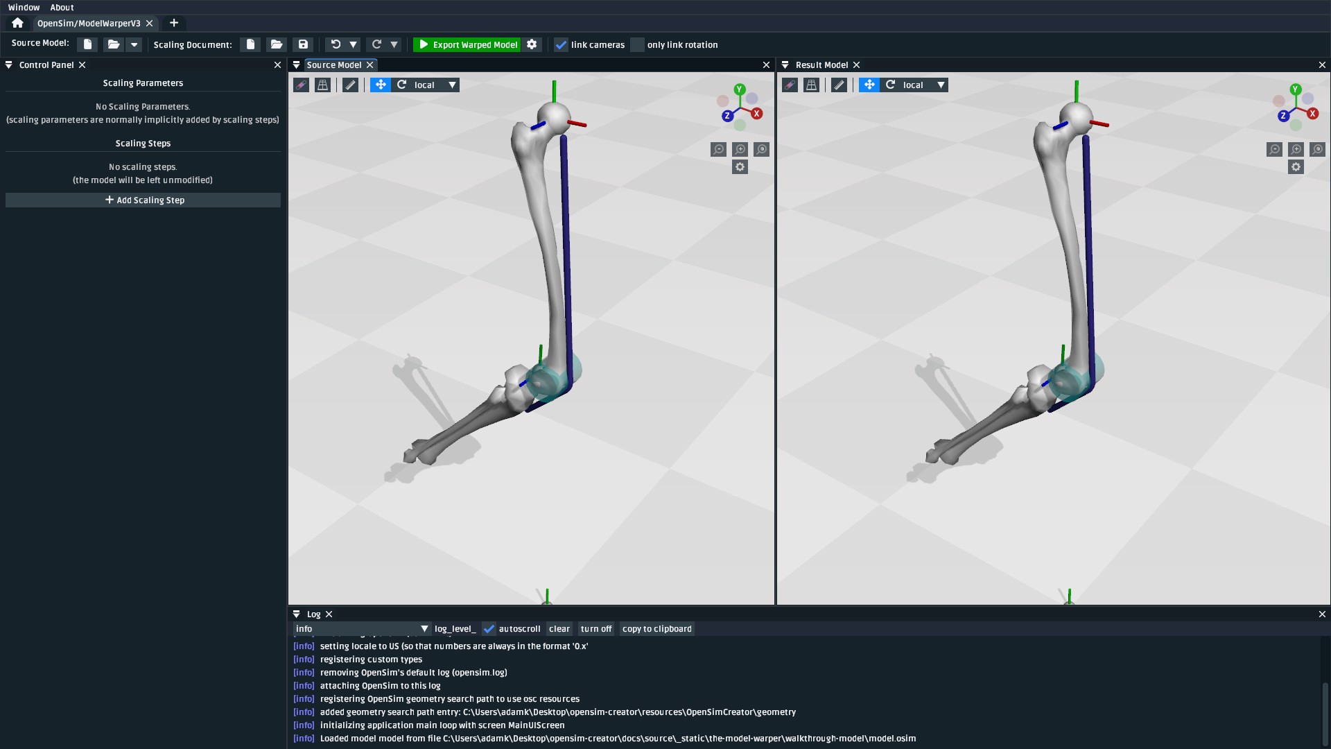
Fig. 110 The model warper after loading make-a-leg_final.osim from Walkthrough Model ZIP. For
clarity, the visual aids of the scene (grid button, top left of a visualizer panel) were
adjusted to disable the floor and enale axis lines.#
Add a Mesh Warping Step#
The model warper is designed around applying scaling steps to the source model one-by-one to produce the result model. Fig. 110 shows the most trivial case of this process, which is to apply no scaling steps and produce a result model that’s identical to the source model.
Building a model warping procedure involves incrementally adding scaling steps that can take the available subject-specific data and apply it to the model. In this case, we have access to CT scans of the source and subject’s femurs, which means we can use the Thin-Plate Spline technique, as described in The Mesh Warper, to warp the source bone mesh using paired landmarks on the femur meshes.
Note
In preparation for the non-linear warping steps, we have already established paired warping landmarks from the source femur mesh in the model to a subject-specific femur in The Mesh Warper. Here’s a screenshot of how that looked:
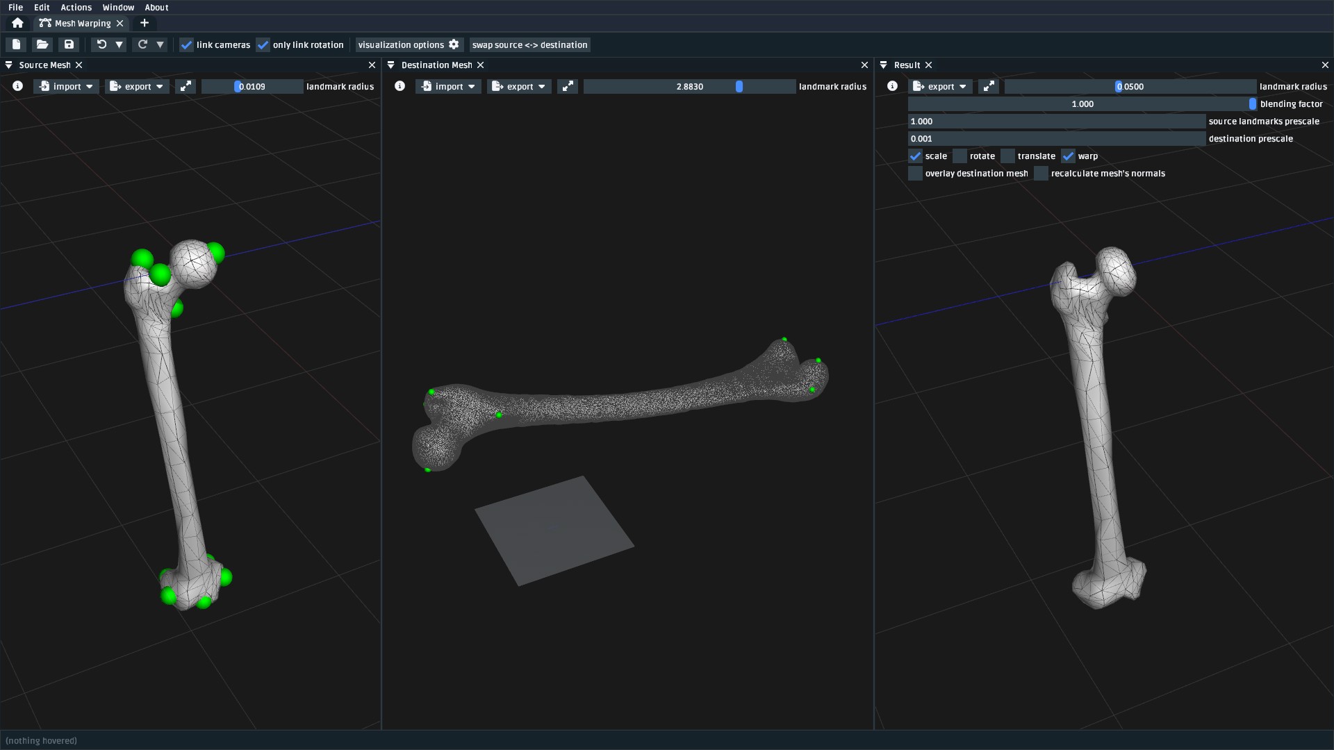
Fig. 111 Screenshot of how landmarks were paired between the source femur (femur_r.obj,
femur_r_warp.landmarks.csv) and the subject femur (subject_femur_r.obj,
subject_femur_r.landmarks.csv) in The Mesh Warper. Rotation and
translation (i.e. reorientation) of the mesh was removed from the TPS warp using the
appropriate checkboxes to correct for subject/scanner orientation. Destination data
was pre-scaled by 0.001 to account for a difference in units between the mesh
files (meters vs. millimeters).#
To warp the femur mesh, add a “Apply Thin-Plate Spline (TPS) to Meshes” scaling step:
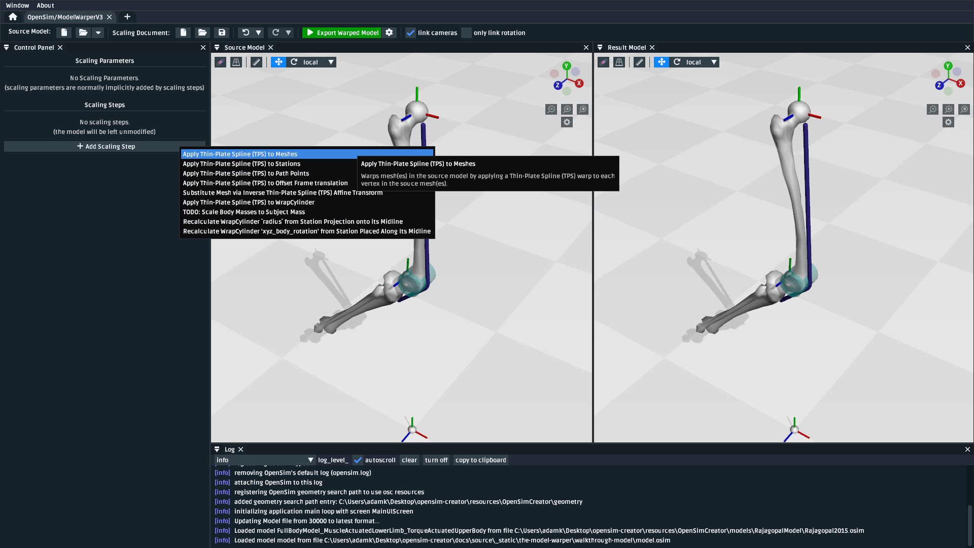
Fig. 112 The “Add Scaling Step” button in the model warper UI opens a menu where you can select the type of scaling step to add to the model warping procedure. In this first step, we add a “Apply Thin-Plate Spline (TPS) to Meshes” step.#
Once you add the scaling step, you will find that the Result Model panel is blanked out with
error messages (Fig. 113). This is because the scaling
step has been added, but the model warping procedure now needs additional information (in this case,
which mesh to warp and the two corresponding .landmarks.csv files) in order to apply the
scaling step to the source model:
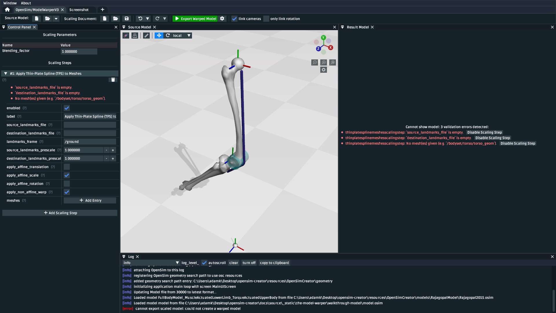
Fig. 113 After adding the “Apply Thin-Plate Spline (TPS) to Meshes” scaling step, the UI stops showing the resultant (output) model because the warping procedure is missing the information it needs to execute the step.#
The model warper’s TPS-based mesh scaling step requires two sequences of landmarks. The
Walkthrough Model ZIP includes a Geometry/ directory that contains femur_r_warp.landmarks.csv
and subject_femur_r.landmarks.csv, which represent femur_r.obj's landmarks and
landmarks subject_femur_r.obj's landmarks respectively.
To fix the errors shown in Fig. 113, you need to fill in the values from Table 1 in the appropriate input boxes. Once you do that, you should end up with something resembling Fig. 114.
Property Name |
Value |
Comment |
|---|---|---|
|
|
Source landmark locations |
|
|
Destination landmark locations |
|
|
The coordinate frame that the two landmark files are defined in. |
|
|
Path within the OpenSim model to the femur mesh component that should be warped by this scaling step. |
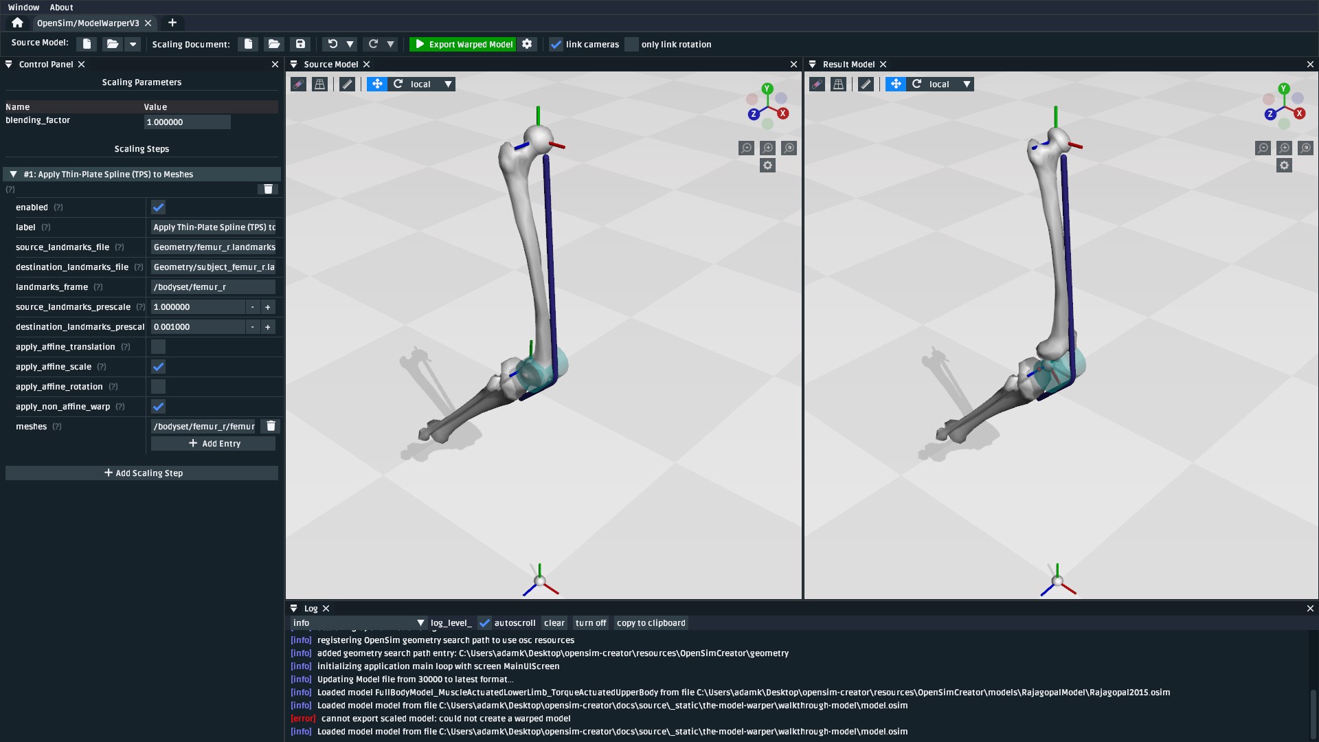
Fig. 114 The model after applying the mesh warping step. The warped mesh is shorter
and slightly twisted when compared to the source mesh. Warping the joint frames, muscle
points, and wrap geometry is handled later in this walkthrough. An easy way to see what
a scaling step is doing is to toggle the enabled button of the step.#
Warping the femur mesh only warps the mesh data while keeping the rest of the model the same. This means the model now looks wrong because the femur mesh is too small compared to the rest of the model. To fix that, we need to scale the remaining components.
Add a Station Warping Step#
The next components we recommend scaling are Stations. The reason why is because, in
this model, StationDefinedFrames were used to define frames on the femur. So if we
warp the stations, we also recompute the femur’s joint frame definitions. See Station Defined Frames
for more information on StationDefinedFrames, and Make a Leg for more
context about how they were added into this model.
To warp the stations, add a “Apply Thin-Plate Spline (TPS) to Stations” scaling step:
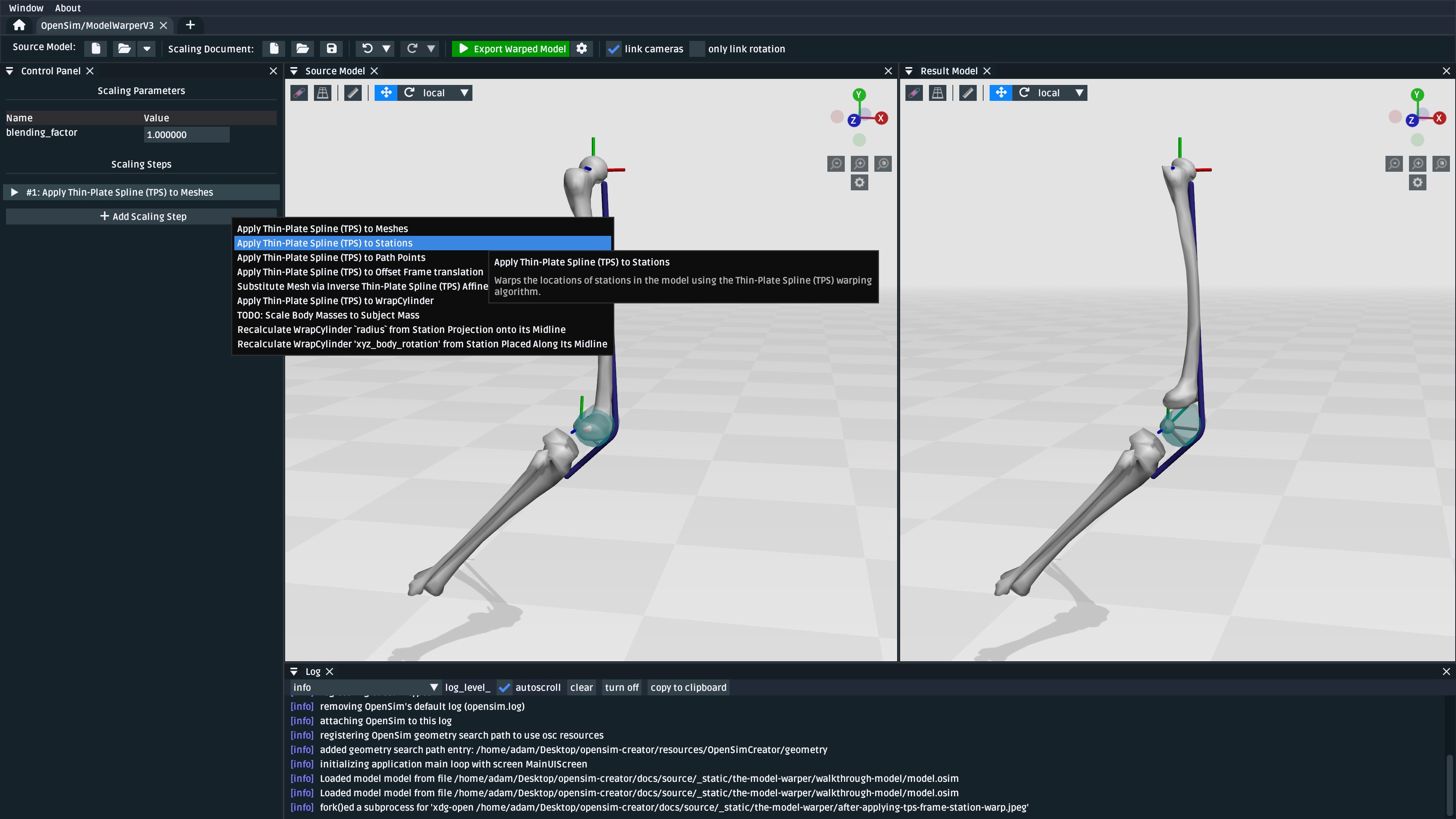
Fig. 115 Use the “Add Scaling Step” menu to add a “Apply Thin-Plate Spline (TPS) to Stations” scaling step.#
Similar to the previous step, you will need to fix the errors shown by filling in the appropriate values. This time, from Table 2:
Property Name |
Value |
Comment |
|---|---|---|
|
|
Source landmark locations |
|
|
Destination landmark locations |
|
|
The coordinate frame that the two landmark files are defined in. |
|
|
Paths within the OpenSim model to the |
After warping the stations, the femur should now be correctly joined to the pelvis and knee, but some further adjustments are still necessary:
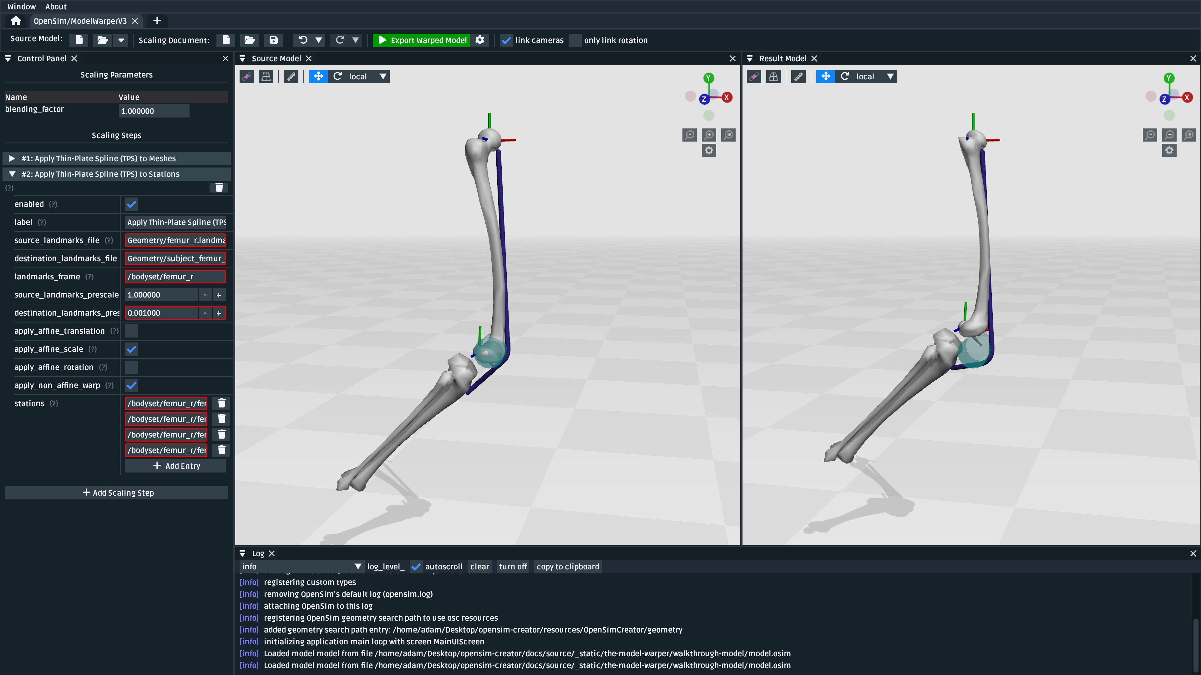
Fig. 116 The model after applying the station warping step to Stations attached to
the femur. Compared to Fig. 114,
it can be seen that the pelvis and knee joint frames are now correctly joined
with the warped femur mesh, but a muscle (glmed_r) is clearly detatched
from the femur.#
Add a Path Point Warping Step#
The muscle point glmed_r-P2 is defined in terms of the femur in the source model, so
it must also be warped. This process is simliar to Add a Station Warping Step.
To warp the muscle path point, add a “Apply Thin-Plate Spline (TPS) to Path Points” scaling step:
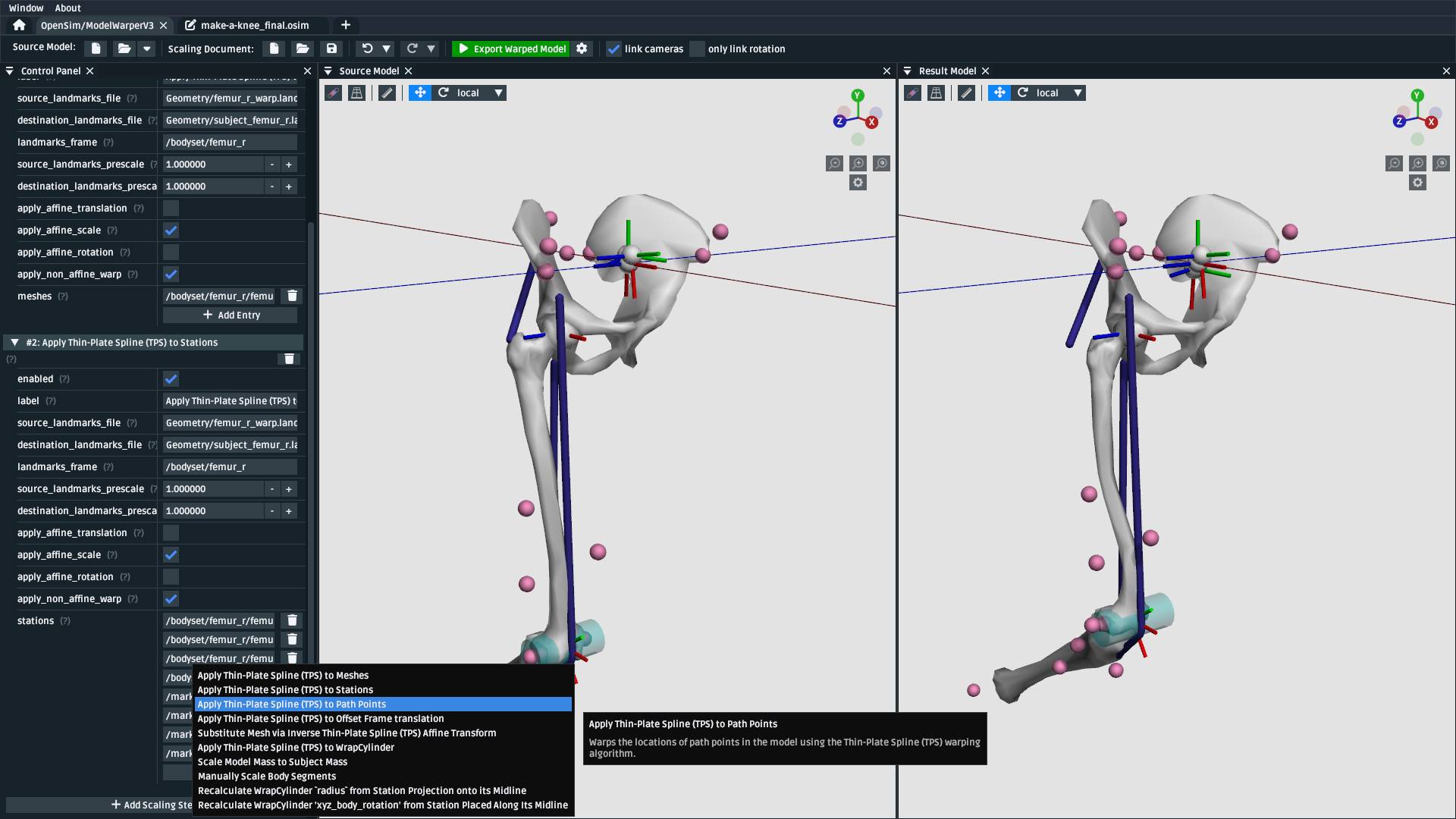
Fig. 117 Use the “Add Scaling Step” menu to add a “Apply Thin-Plate Spline (TPS) to Path Points” scaling step.#
Similar to the previous step, you will need to fix the errors shown by filling in the appropriate values. This time, from Table 3:
Property Name |
Value |
Comment |
|---|---|---|
|
|
Source landmark locations |
|
|
Destination landmark locations |
|
|
The coordinate frame that the two landmark files are defined in. |
|
|
Path within the OpenSim model to the muscle path point(s) that should be warped. |
After warping glmed_r-P2, you should see that it is now correctly attached to the warped femur:
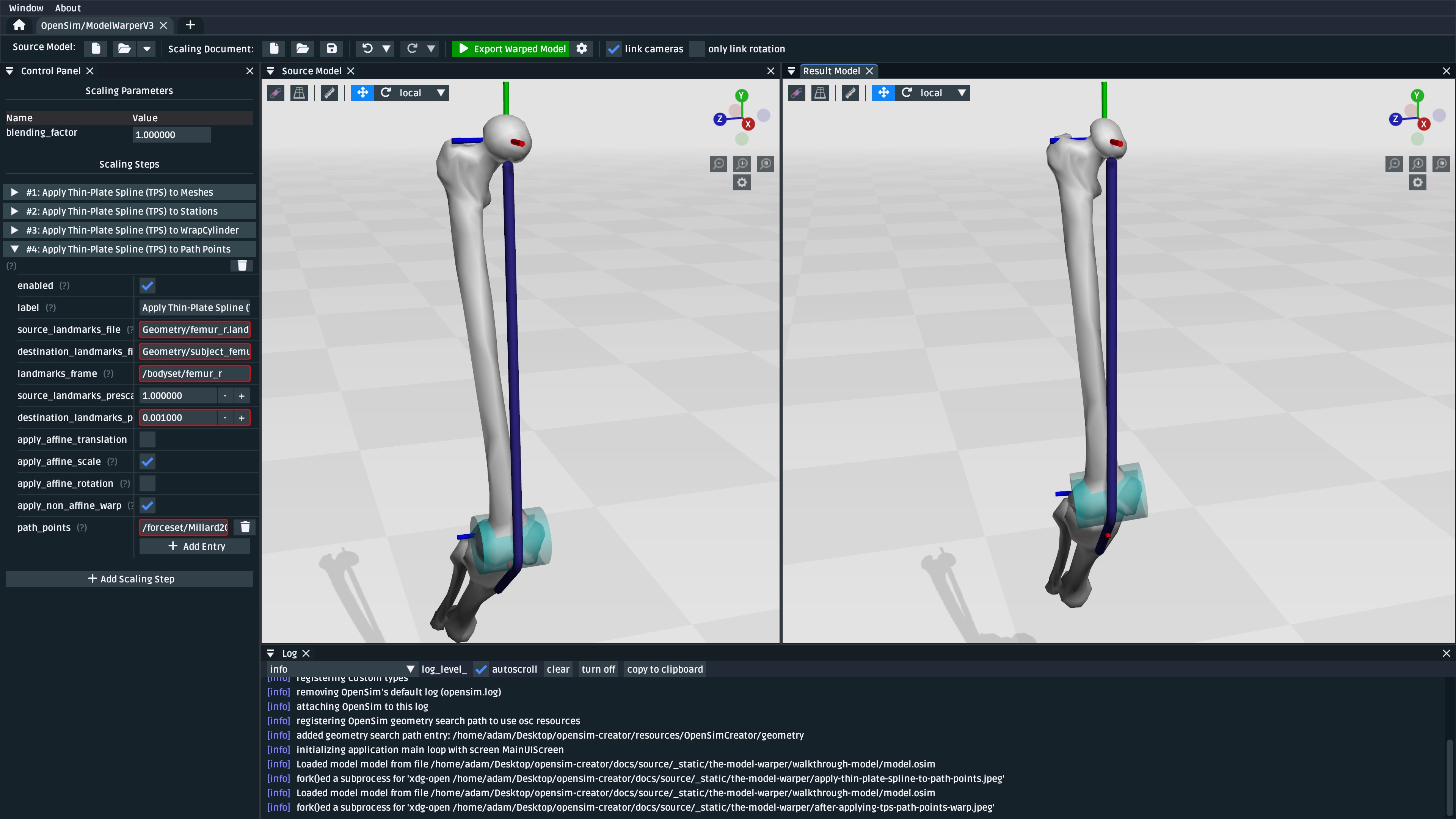
Fig. 118 The model after applying the path point warping step to glmed_r-P2. Compared
to Fig. 116, it can be seen that the
glmed_r muscle now correctly attaches to the warped femur mesh.#
Manually Scale Other Body Segments#
To keep this tutorial brief, we will only non-linearly warp the femur. If warping was required
on the other body segments, the same steps would be used. Here, the other body segments (pelvis, tibia_r),
will be manually scaled with a scale factor. This is equivalent to the scaling that’s already
available in OpenSim.
Note
The scale factors used in this section were approximated using the scale and inverse
kinematics tools in OpenSim on experimental marker data collected from the subject. This
is a common way to scale models in OpenSim. However, we have omitted scaling femur_r
here because it has already been warped by the other Thin-Plate Spline (TPS) scaling
steps.
If you’re curious about the difference between linear and non-linear scaling, the equivalent
femur_r linear scale factors would be (0.853983, 0.826068, 0.839395). You could even
add a manual scaling step for femur_r here and disable the TPS warping steps to create
a side-by-side comparison of the two scaling techniques.
To manually scale pelvis, add a “Manually Scale Body Segments” scaling step:
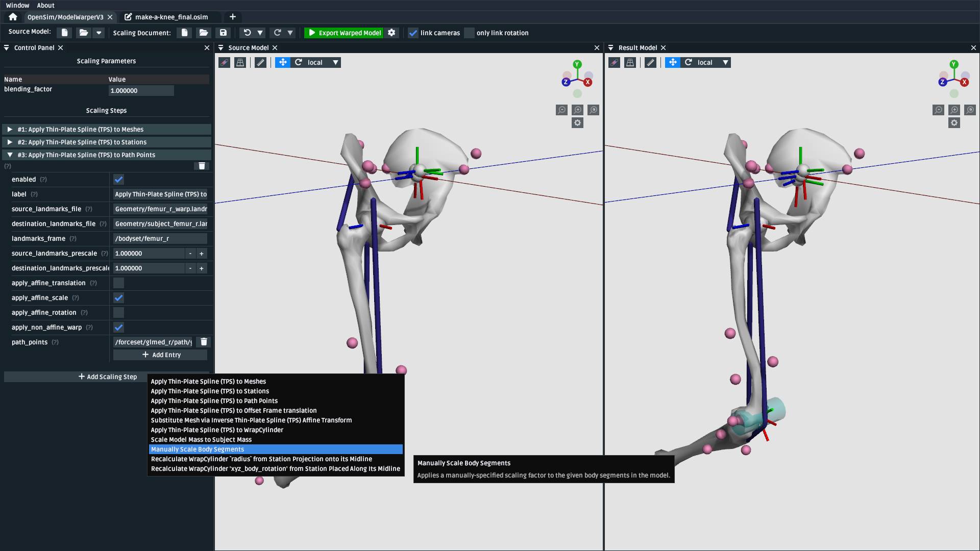
Fig. 119 Use the “Add Scaling Step” menu to add a “Manually Scale Body Segments” scaling step.#
And add /bodyset/pelvis to bodies, followed by setting the scale_factors to
(0.75828, 0.73484, 0.771248).
Next, add a second “Manually Scale Body Segments” scaling step with /bodyset/tibia_r
in bodies and scale_factors of (0.776503, 0.849965, 0.890335). You should
end up with two manual scaling steps for the other two body segments, which
should scale the rest of the model to roughly match the femur:
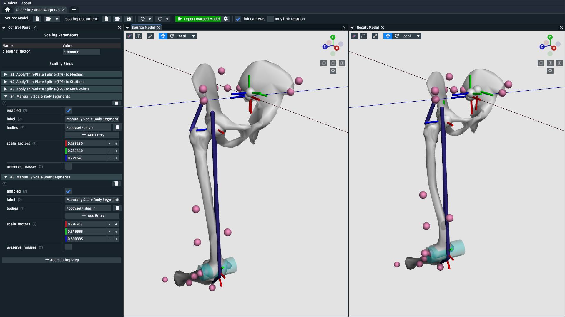
Fig. 120 The model after applying manual scaling steps to pelvis and tibia_r. Compared
to Fig. 118, it can be seen that the
pelvis and tibia are smaller and more closely match the size of the (warped) femur.#
Scale Wrap Cylinder#
The model contains a WrapCylinder called knee_wrap, which should also be scaled to
account for the femur warp.
The TPS technique can only be used on points, not shapes like cylinders. Therefore, we will use a heuristic scaling step that recomputes the radius of the cylinder as the distance between the cylinder’s axis (midline) and a station in the model. That way, we can TPS-warp a station and use its warped location to compute a cylinder radius that more closely matches the warped geometry.
To scale knee_wrap’s radius, add a “Recalculate WrapCylinder radius from Station
Projection onto its Midline” scaling step:
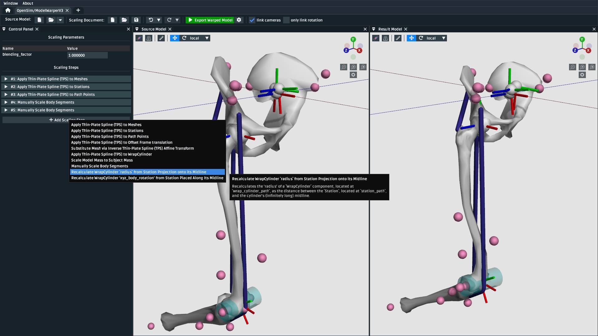
Fig. 121 Use the “Add Scaling Step” menu to add a “Recalculate WrapCylinder radius from Station Projection onto its Midline” scaling step.#
And then choose /bodyset/femur_r/knee_wrap_surface_point as the station_path and /bodyset/femur_r/knee_r_frame/wrapobjectset/knee_wrap
as the wrap_cylinder_path, which should rescale the cylinder to more closely match
the warped femur geometry:
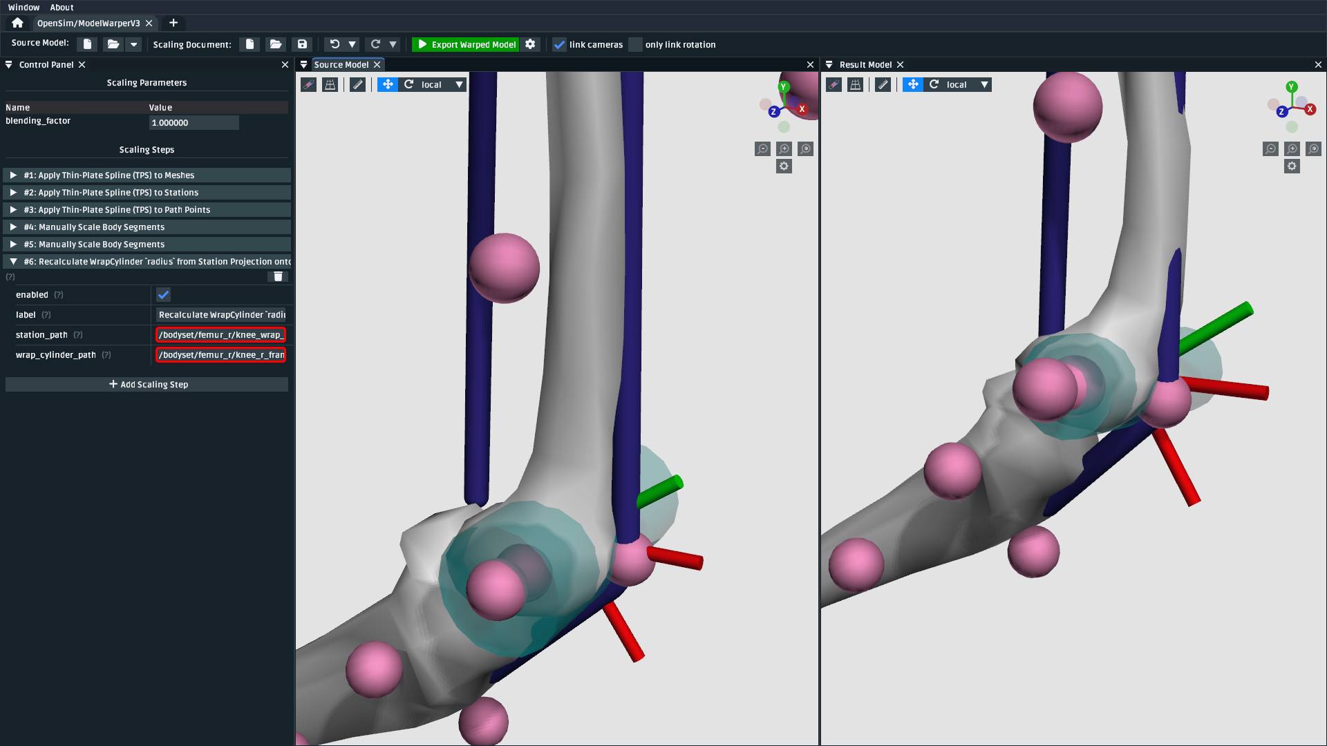
Fig. 122 The model after recalculting the knee wrap’s radius. Without this scaling step, the knee wrap
is larger than it should be. Note: recfem_r clips through the femur bone because the mesh
warp, in this case, is rather extreme (choosing warp landmarks is, itself, an art).#
Export Result Model#
With everything warped, we can now export the result model as a new OpenSim model.
Exporting was possible at any point in the walkthrough where there wasn’t any error messages shown in the result model panel, and it can be good idea to occasionally export the model to explore what scaling steps are missing. The export process involves clicking the “Export Warped Model” button, located in the toolbar:
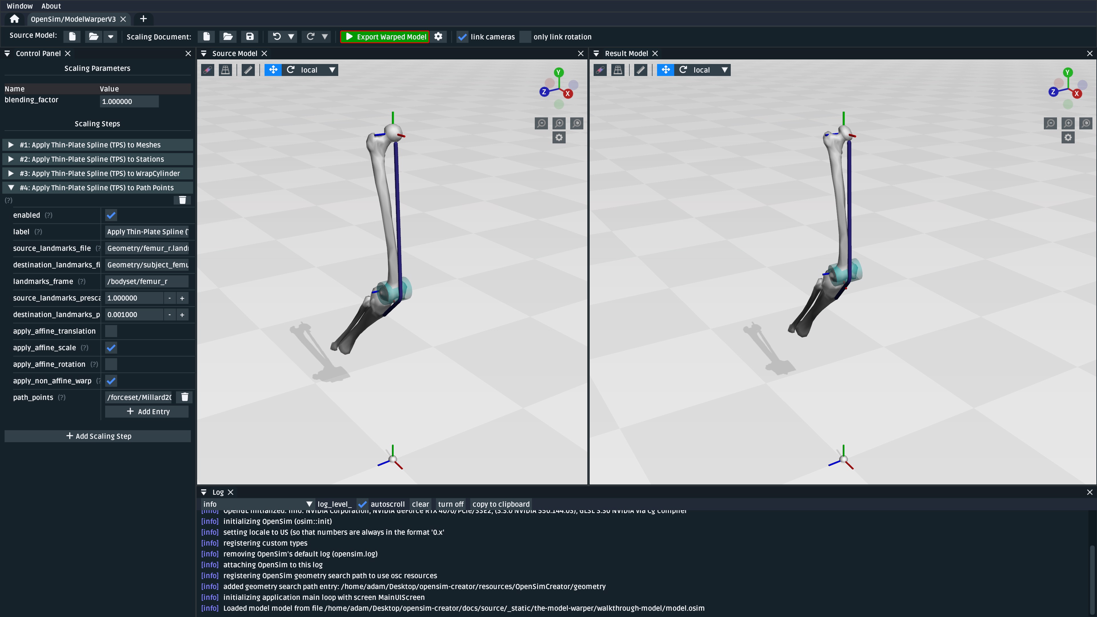
Fig. 123 To export the warped result model, press the green “Export Warped Model” (circled in red). This will apply all scaling steps to the source model and create a new OpenSim model in memory that can be edited, examined, or saved in the model editor. The gear icon (⚙️) next to the button shows some customization points (e.g. where the exporter should write warped mesh data).#
Warning
If your warped model needs to be compatible with OpenSim 4.5 and earlier, you should also enable the “Bake StationDefinedFrames” option using the gear icon (⚙️) next to the “Export Warped Model” button:
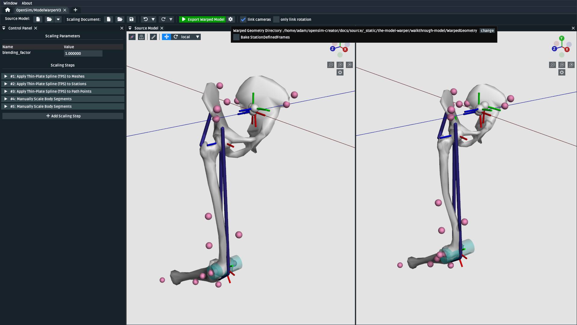
Fig. 124 The “Bake StationDefinedFrames” checkbox causes the model warper to also convert all
StationDefinedFrames in the source model into PhysicalOffsetFrames, which are
compatible with OpenSim 4.5 and earlier.#
This will then open a standard OpenSim model editor tab (Fig. 125, the
same workflow that’s used to edit an .osim file). You can then save the .osim file, if you’d
like, or investigate/edit the resulting model further.
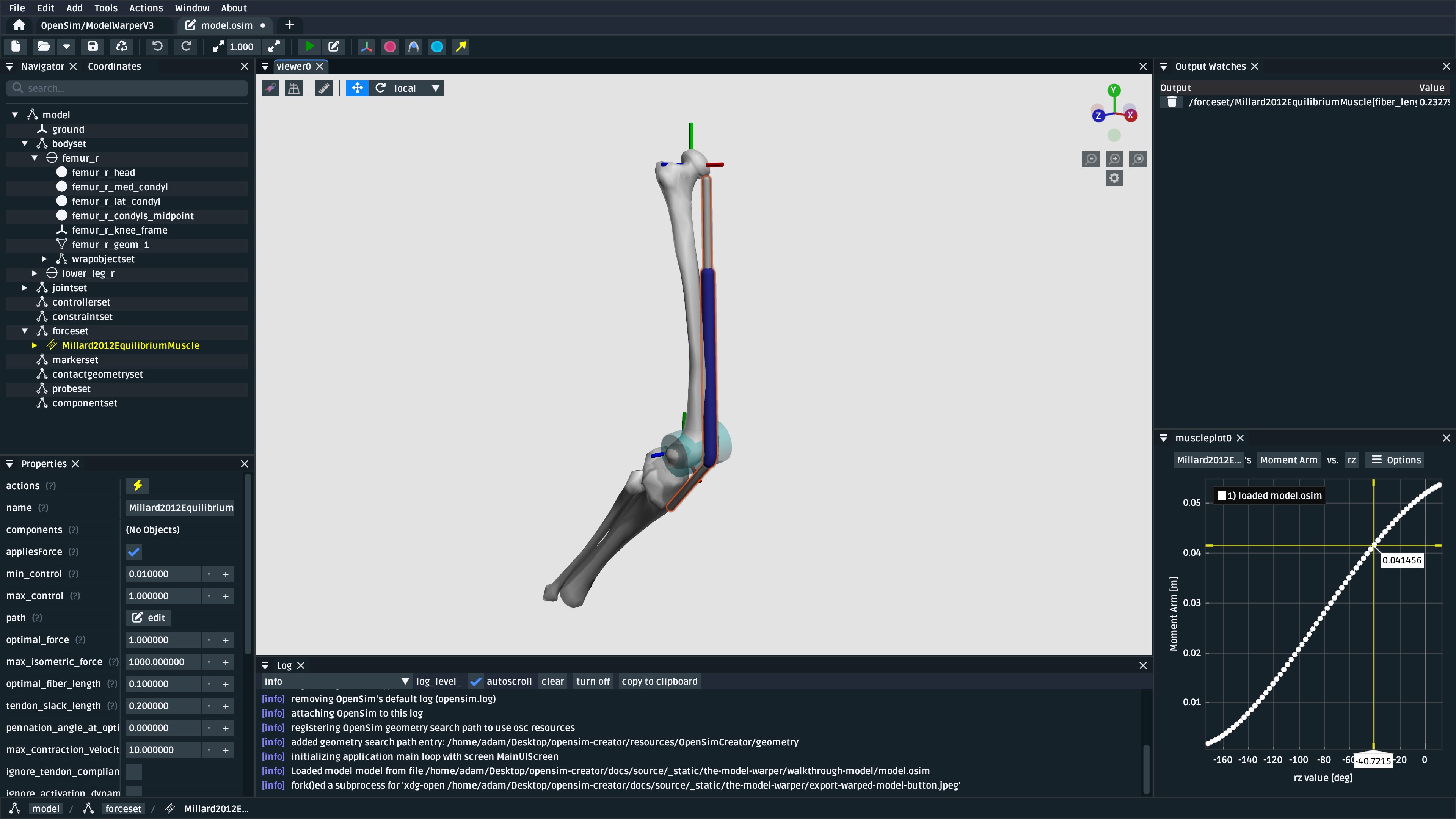
Fig. 125 The final warped model after exporting it, which opens it in the model editor workflow. The exported
model is only held in memory, rather than written to disk, so you’ll need to save it. All the usual
.osim model editing capabilities are available in this workflow (e.g. live muscle moment arm
plotting, as pictured), so you can also perform any final investigations/edits here before saving
the model.#
Summary#
In this tutorial, we built a subject-specific warping pipeline using the model warper in OpenSim Creator. We warped the femur with Thin-Plate Spline (TPS) techniques, adjusted stations and muscle path points to maintain correct anatomical relationships, and manually scaled the pelvis and tibia. By incrementally adding and customizing scaling steps, we created a reusable pipeline that accounted for non-linear changes such as femoral torsion.
Main takeaways:
We combined multiple scaling steps (mesh, station, path point, manual) into one pipeline.
TPS warping handled localized, non-linear changes while manual scaling adjusted remaining segments.
Using
StationDefinedFramesensured joint frames updated correctly during warping.The result was a reusable, exportable OpenSim model tailored to subject-specific data.
Next Steps#
Validate and analyze the warped model. Leverage OpenSim Creator’s built-in tools to plot and monitor model quantities (e.g., joint frames, muscle paths, moments). You can also export your warped model and examine it in the full OpenSim GUI, which provides additional analysis workflows such as Static Optimization, Computed Muscle Control, and Inverse Dynamics.
Enhance model fidelity by scaling inertial properties. Consider expanding your pipeline to include mass and inertia scaling of the rigid body segments—a capability that isn’t yet supported natively in OpenSim Creator. Adjusting these properties using external tools or manual methods can significantly improve dynamic simulation accuracy (e.g., joint moments and balance).
Explore muscle parameter scaling for realistic muscle dynamics. To refine the muscular behavior in your model, you can adjust key muscle parameters—such as maximum isometric force, optimal fiber length, tendon slack length, and contraction velocity—which are available in OpenSim’s muscle components.