
8. Make a Lower Leg#
Warning
This tutorial is new ⭐, and uses StationDefinedFrames, which require OpenSim >= v4.5.1.
The content of this tutorial should be valid long-term, but we are waiting for OpenSim GUI
v4.6 to be released before we remove any “experimental” labelling. We also anticipate
adding some handy tooling around re-socketing existing joints and defining StationDefinedFrames.
In this tutorial, we will be making a model of a lower leg using OpenSim Creator:
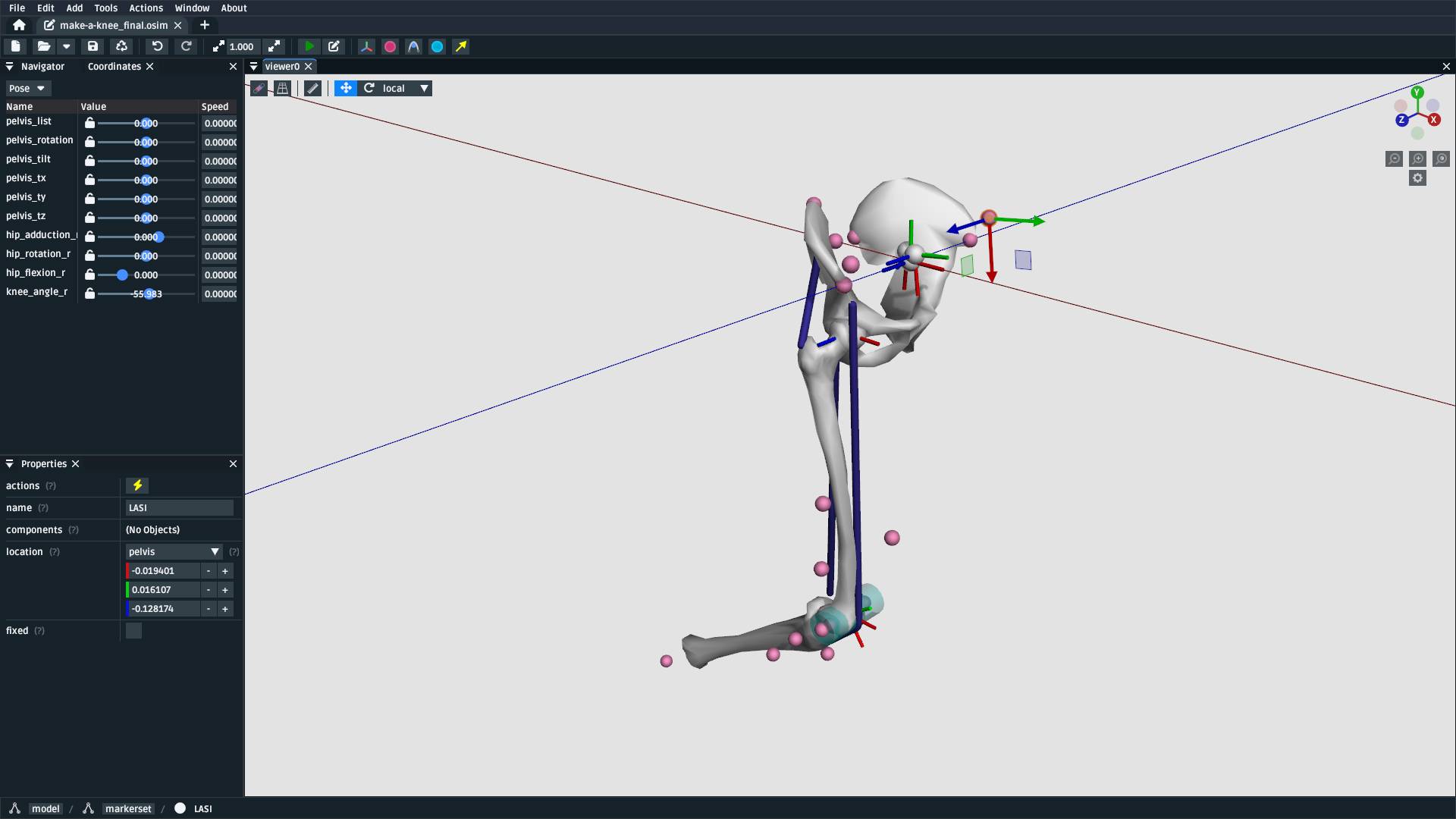
Fig. 8.1 The model created by this tutorial. It contains three bodies, two joints, three muscles, and a wrap cylinder. This covers the basics of using OpenSim Creator’s model editor to build a model with biological components (see Make a Bouncing Block for a more mechanical example).#
This tutorial will primarily use the model editor workflow to build a model from scratch that contains some of the steps/components necessary to build a human model. In essence, the content here will be similar to that in Make a Bouncing Block, but with a focus on using landmark data, Station Defined Frames, and wrap surfaces to build a model of a biological system.
8.1. Prerequisites#
This tutorial assumes you:
Have a basic working knowledge of OpenSim, which is covered in Make a Pendulum and Make a Bouncing Block.
(optional) The modelling process will also include adding a
StationDefinedFrameto the model. The details of how they work is explained in Station Defined Frames.(optional) The building process uses externally-provided landmarks from CSV files (e.g.
femur_r.landmarks.csv). If you would like to know how to manually place landmarks on a mesh, we recommend reading through The Mesh Importer.
8.2. Topics Covered by this Tutorial#
Creating an OpenSim model by adding bodies and joints.
Adding
StationDefinedFrames to the model in order to define anatomically representative joint frames.Adding a muscle to the model.
Adding a wrap surface to the model and associating muscles to that surface.
8.3. Download Resources#
In order to follow this tutorial, you will need to download the associated
resources (download here)
and unzip them on your computer.
8.4. Create a New Model#
Create a new model, as described in Make a Pendulum (Create a New Model).
8.5. Add a pelvis Body#
Add a pelvis body. For this model, use the following parameters:
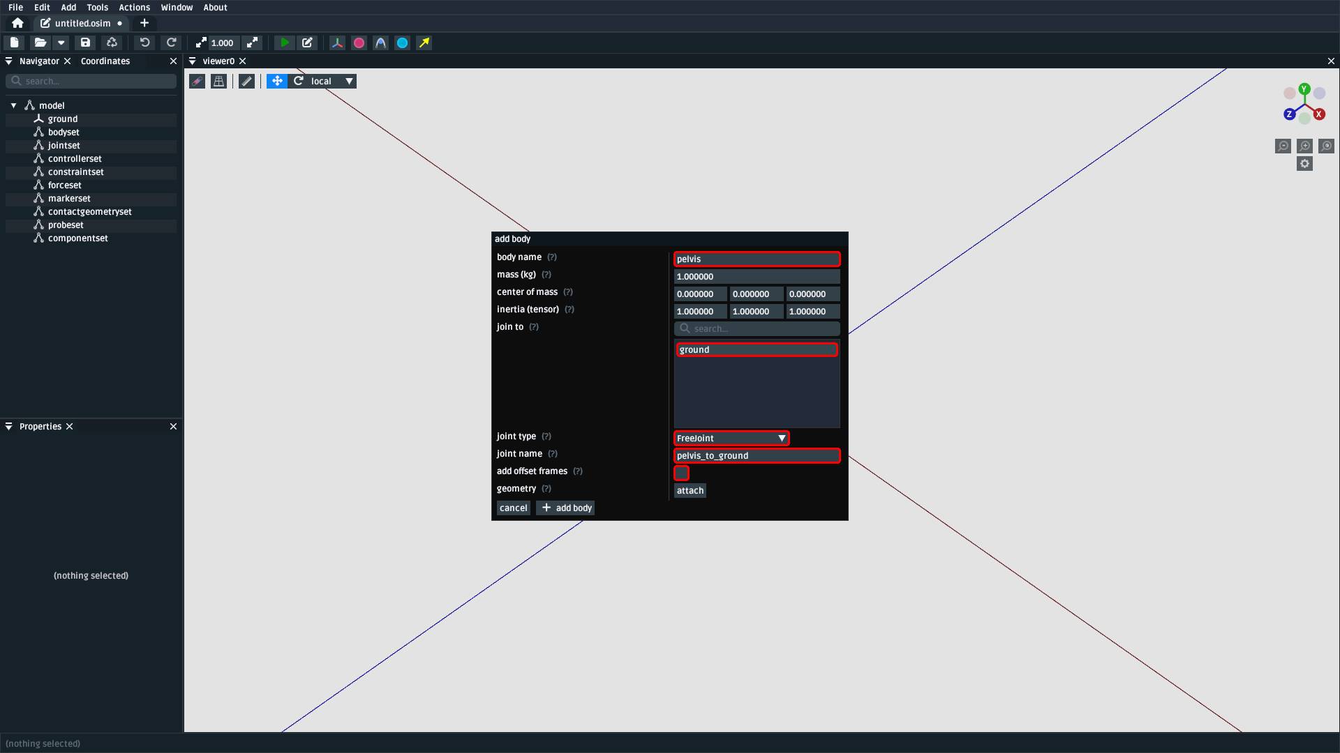
Fig. 8.2 Create a body called pelvis. The mass and inertia can be handled later.
pelvis should directly (no offset frames) be joined to ground with
a FreeJoint called pelvis_to_ground. Pelvis meshes are attached in
the next step.#
Adding bodies is explained in more detail in Add a Body with a WeldJoint and Create the Foot.
8.6. Attach Pelvis Meshes to the pelvis Body#
The resources zip described in Download Resources contain two
separate pelvis meshes for the left- and right-side. For this model, we are simplifying
the pelvis to a single rigid body (pelvis). Both meshes need to be attached to it.
To attach meshes to pelvis, right-click it in the Navigator panel and use
the Add > Geometry context menu to attach each pelvis mesh:
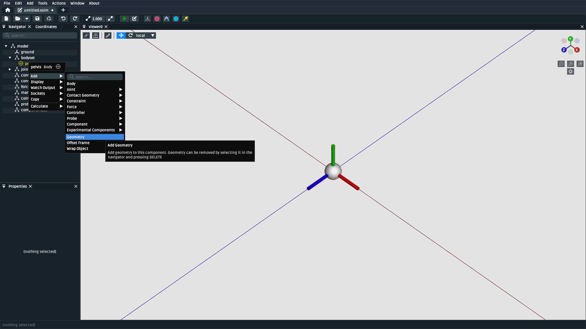
Fig. 8.3 Use pelvis’s context menu to Add > Geometry to it, then select one
of the pelvis meshes (pelvis_l.obj or pelvis_r.obj). Repeat this process
for the other pelvis mesh.#
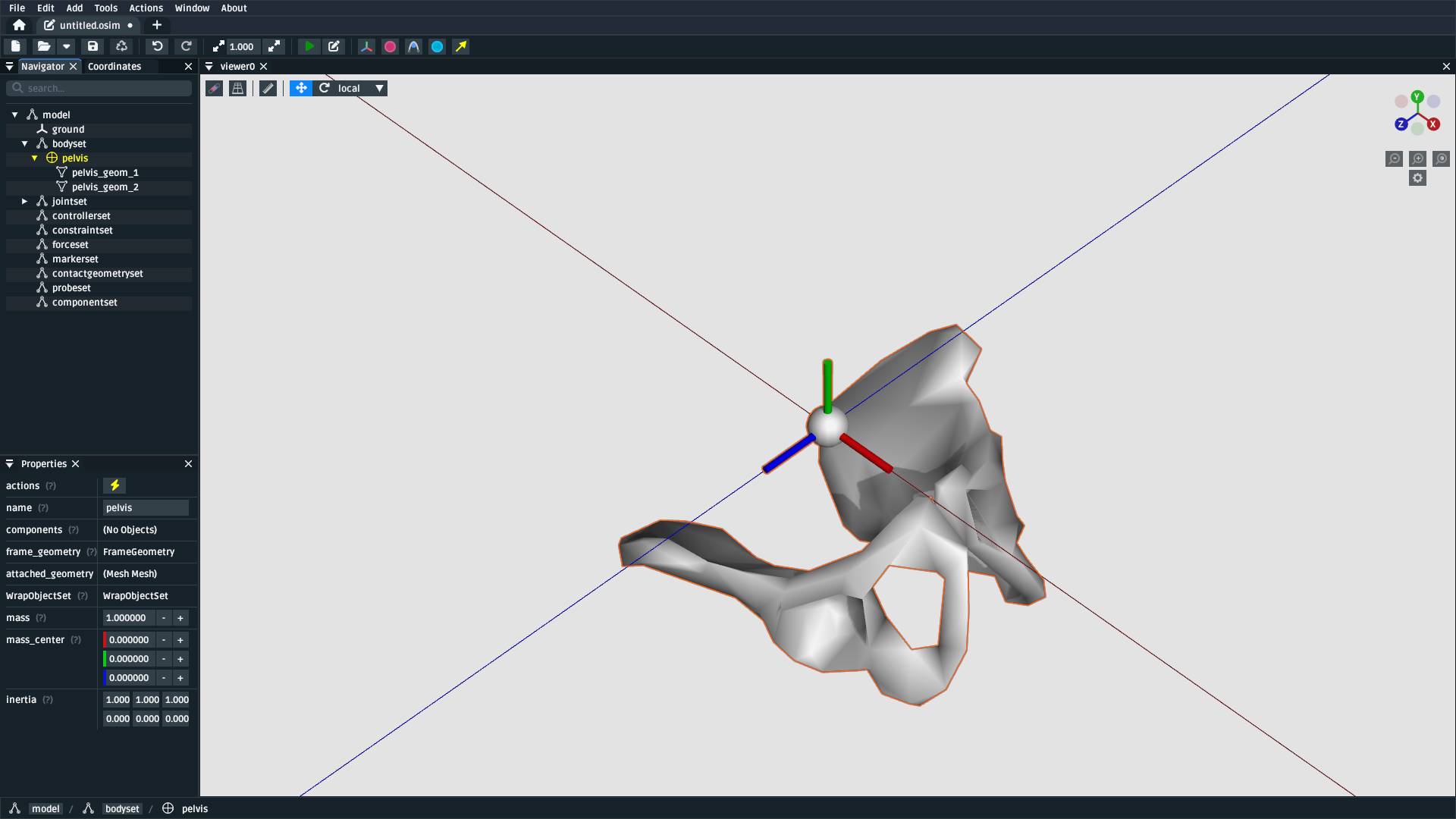
Fig. 8.4 The model after attaching both pelvis_l.obj and pelvis_r.obj to the
pelvis body. For context, assume the reference subject was lying down
when these bones were scanned. A major part of the model building procedure involves defining
frames that transform experimental measurements into standardized coordinate
systems.#
8.7. Import Pelvis Landmarks#
This model will use a landmark-defined approach to define the pelvis frame and
the hip/knee joint frames (explained in Station Defined Frames). To do
that, we’ll initially import landmarks on the pelvis body and (later) on the
femur body. The landmarks we will use roughly correspond to those explained
in Grood et. al.; however, our knee joint definition will use the Z axis to
define knee extension/flexion (Grood et. al. use the X axis) because OpenSim’s
PinJoint always uses the Z axis for rotation.
To import the landmarks, you can use the point importer in the model editor from
the top menu bar, located at Tools > Import Points. It will show a popup
that you can use to import the pelvis landmarks file (pelvis.landmarks.csv) as
markers that are attached to the pelvis body:
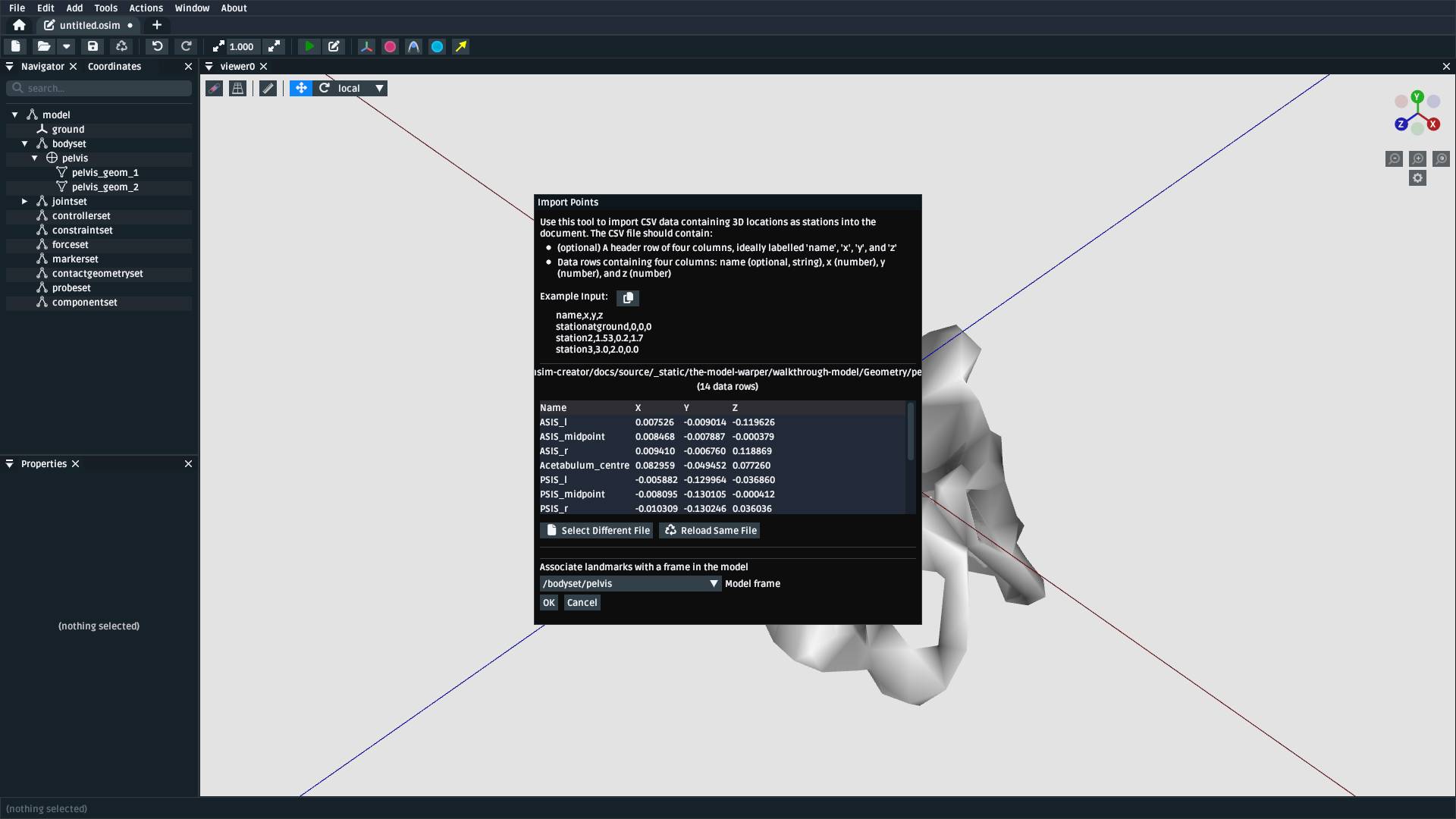
Fig. 8.5 The Import Points dialog, after selecting pelvis.landmarks.csv. Make sure to
choose /bodyset/pelvis as the body to attach the landmarks to. Otherwise, they
will end up attached to ground.#
8.8. Add a StationDefinedFrame on pelvis for the Pelvis Frame#
Now that the appropriate pelvis landmarks are imported into the model, you can
now define a StationDefinedFrame on the pelvis that describes the model’s top-level
transform. OpenSim models tend to be oriented such that Y points up and X points forwards.
Adding a pelvis_frame is described in the following two figures:
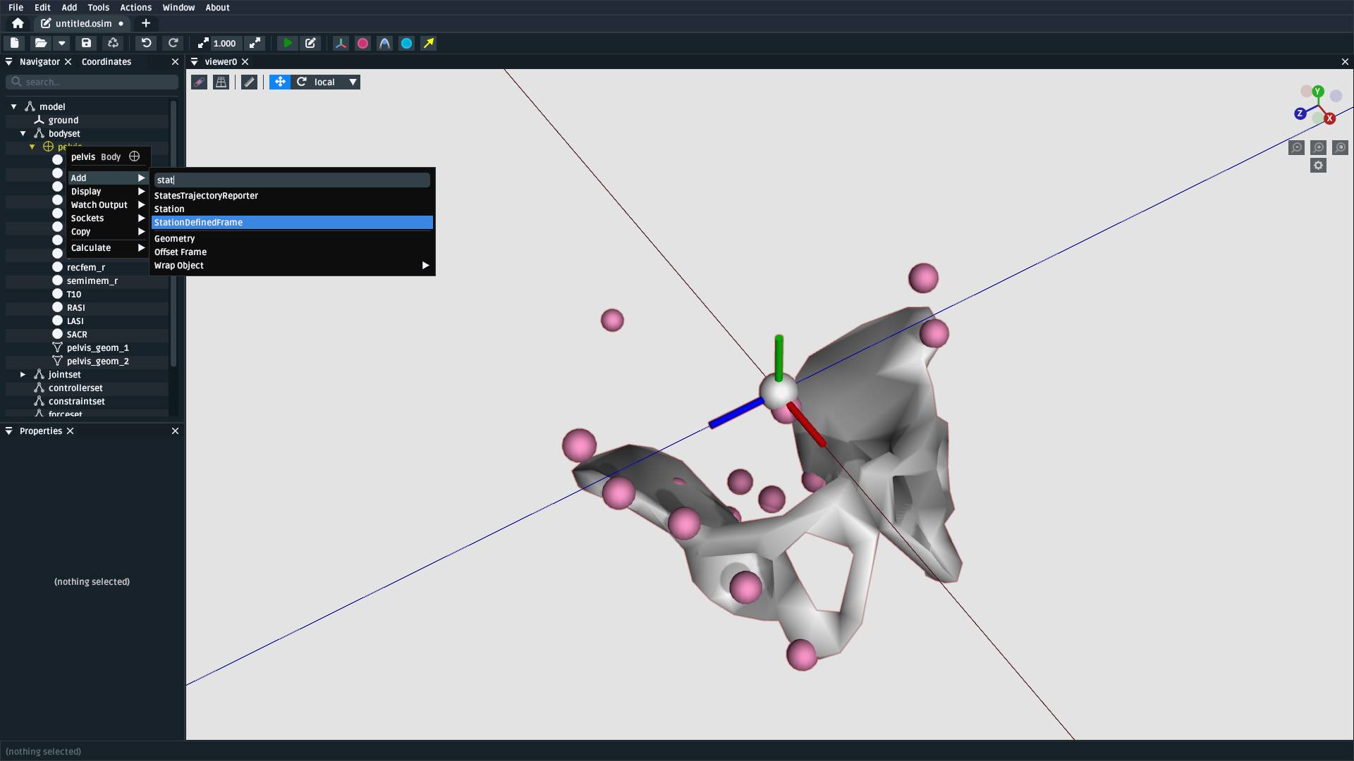
Fig. 8.6 A StationDefinedFrame can be added as a child of pelvis by right-clicking
the pelvis component in the Navigator panel and using the Add menu to
add a StationDefinedFrame.#
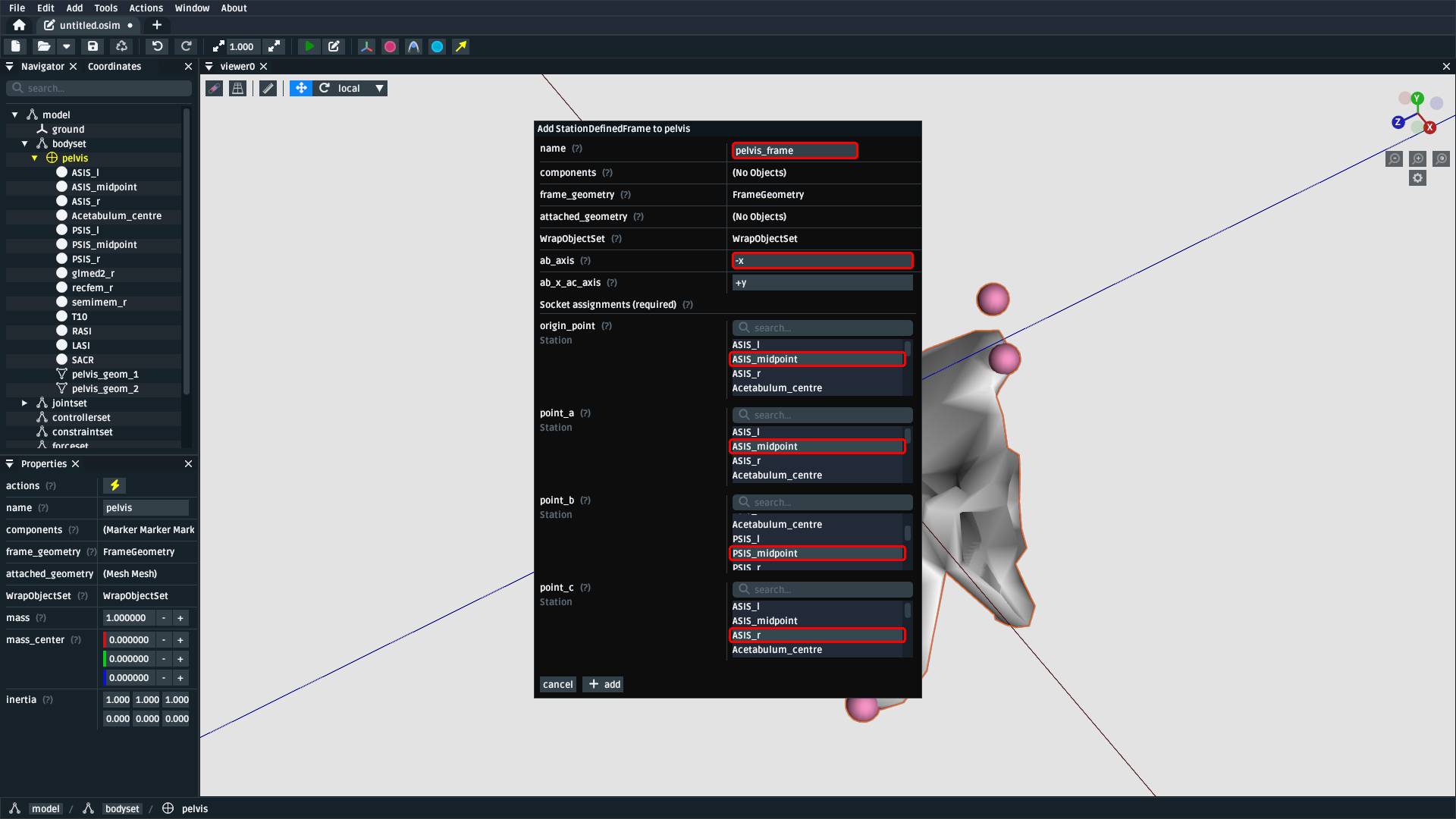
Fig. 8.7 When creating the StationDefinedFrame, call it pelvis_frame, make ASIS_midpoint
the frame origin_point and point_a, PSIS_midpoint point_b, and ASIS_r point_c
Additionally, ensure that ab_axis is -x and ab_x_ac_axis is +y. The
Station Defined Frames page explains StationDefinedFrames in more detail.#
8.9. Reassign pelvis_to_ground to the StationDefinedFrame#
With a “root” StationDefinedFrame created on pelvis, you can now reassign the
pelvis-to-ground joint (pelvis_to_ground) to use pelvis_frame instead of pelvis.
To do that, right-click the appropriate joint in the Navigator panel and use the
Sockets menu to reassign its child_frame:
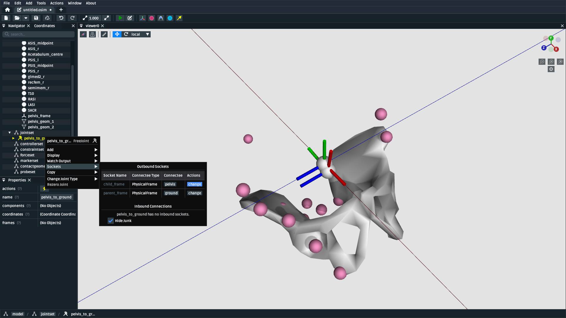
Fig. 8.8 Use the Navigator panel to find and right-click pelvis_to_ground, then
find child_frame in the Sockets menu and change it to
pelvis_frame.#
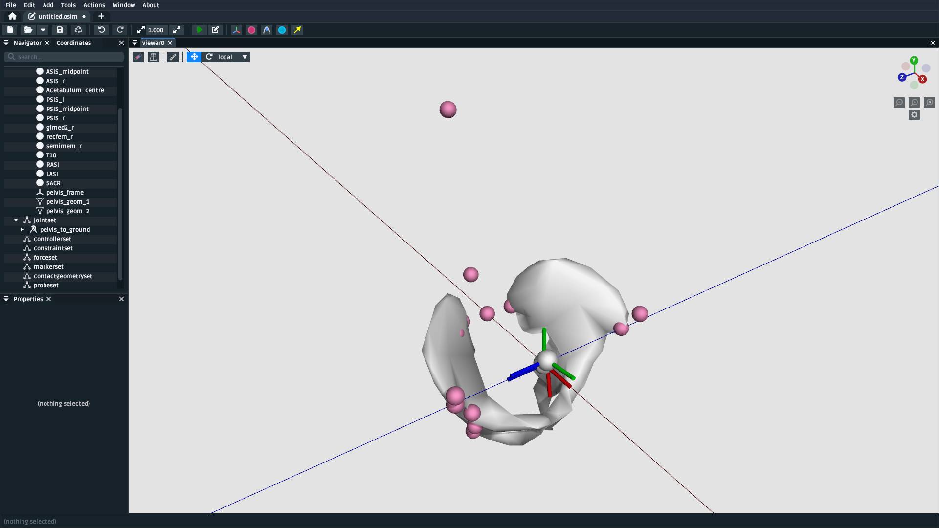
Fig. 8.9 Reassigning the joint this way causes the pelvis to be located and oriented similarly to existing OpenSim models.#
8.10. Add a StationDefinedFrame on pelvis for the Hip Joint#
The next step is to describe where the right hip joint should be placed on the
pelvis. This process is the same as Add a StationDefinedFrame on pelvis for the Pelvis Frame, but we instead
define a StationDefinedFrame on pelvis called hip_r_frame as follows:
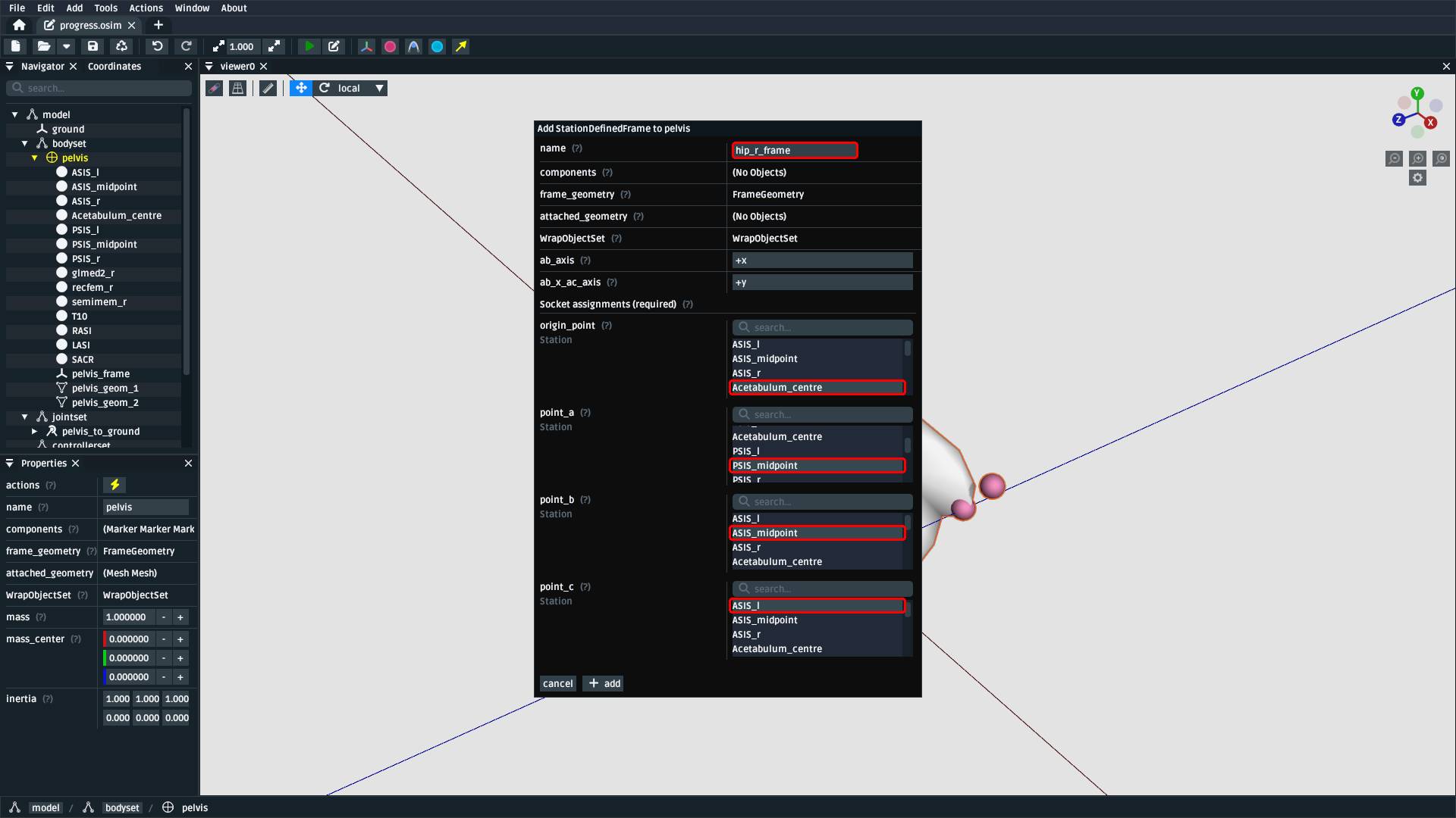
Fig. 8.10 Right-click the pelvis body and add a StationDefinedFrame. Call it
hip_r_frame, make Acetabulum_centre the frame origin_point,
PSIS_midpoint point_a, ASIS_midpoint point_b, and ASIS_l
point_c. Additionally, ensure that ab_axis is +x and ab_x_ac_axis
is +y.#
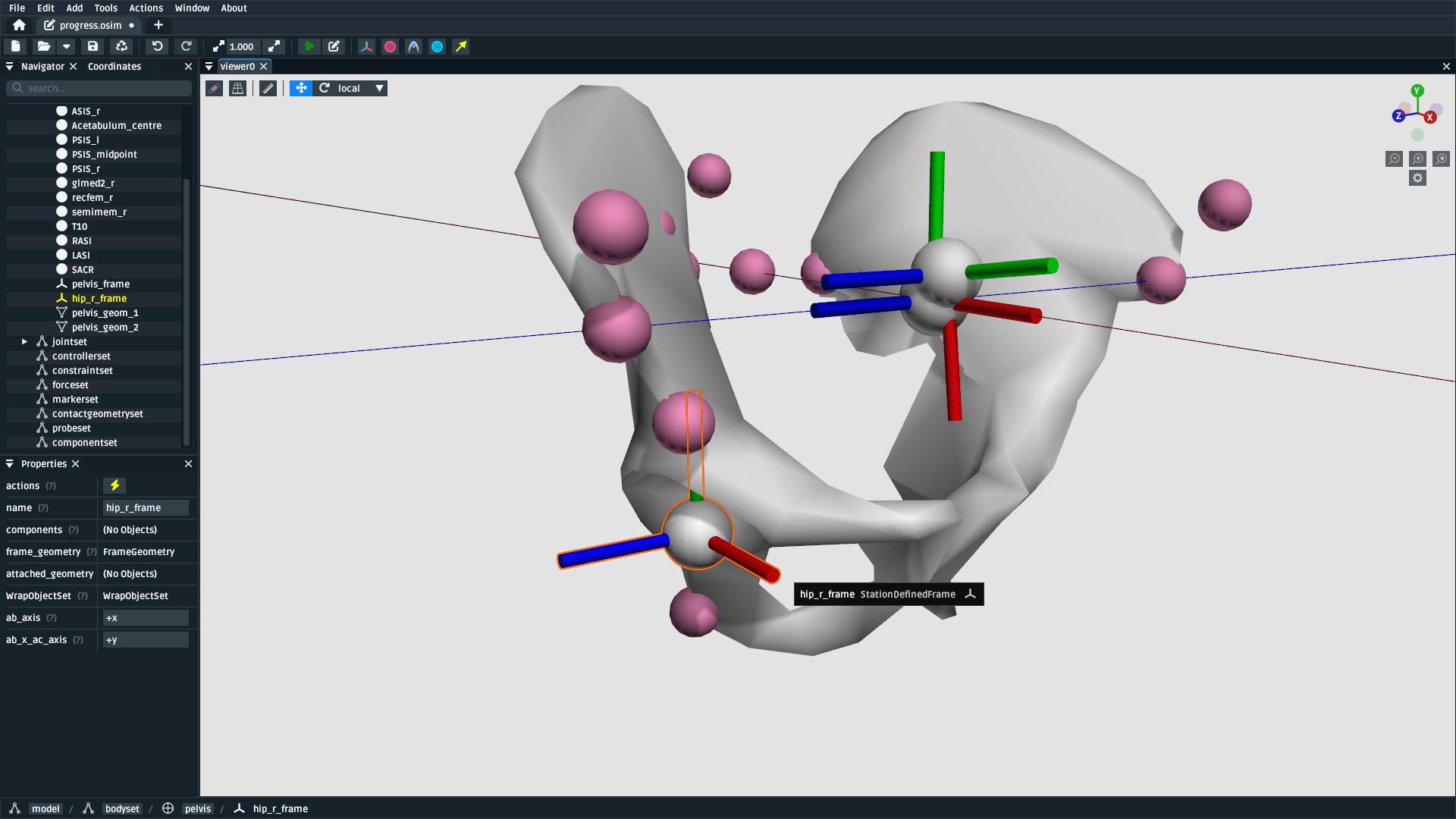
Fig. 8.11 The relationship between the landmarks defines the hip_r_frame (highlighted).#
8.11. Add a Femur Body#
Add a femur body with the femur mesh (femur_r.obj) attached to the hip_r_frame
we just defined. For this model, use the following parameters:
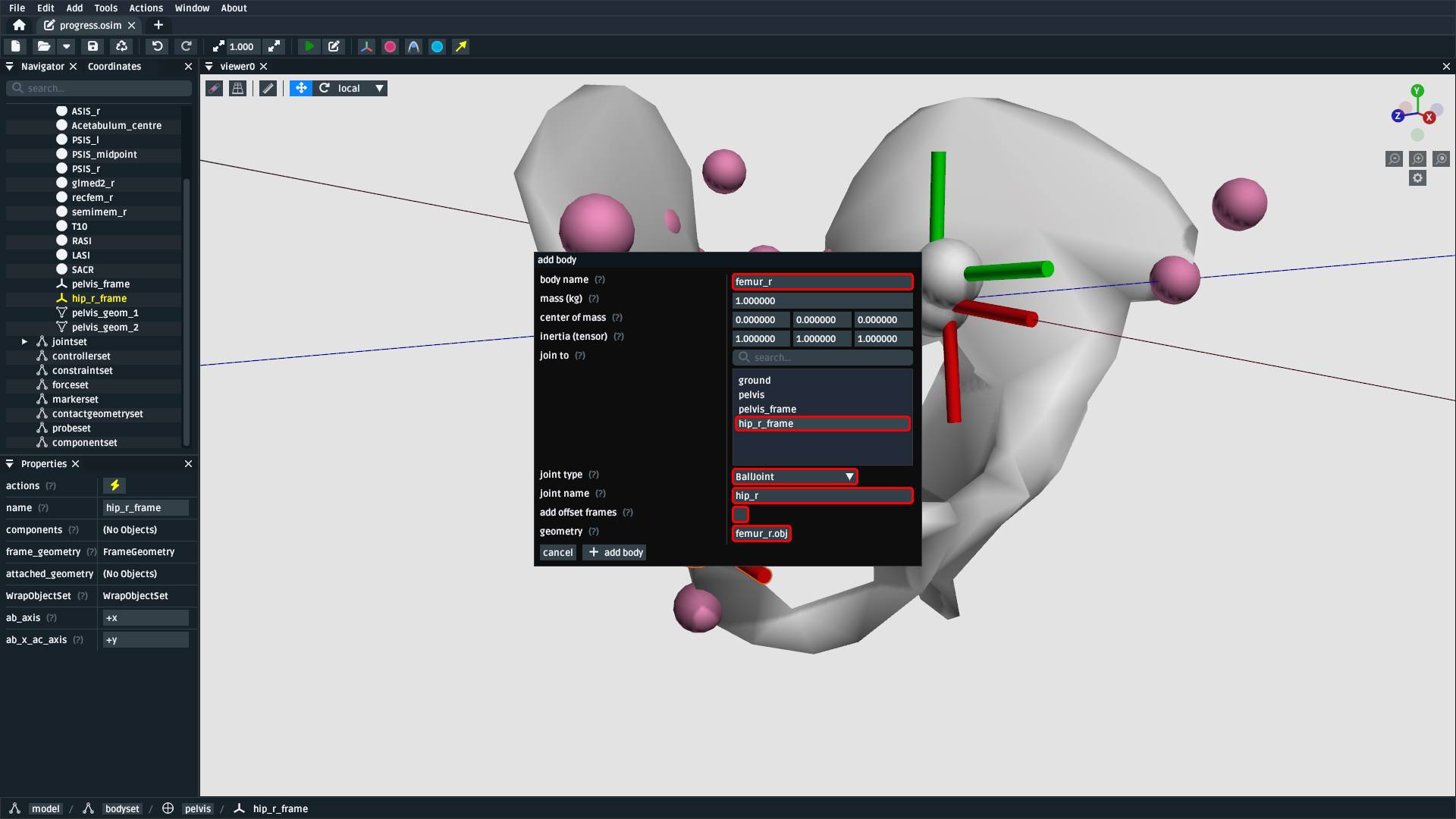
Fig. 8.12 Create a body called femur_r and join it directly (no offset frames) to
hip_r_frame with a BallJoint called hip_r. Attach femur_r.obj
geometry to it.#
Adding bodies is explained in more detail in Add a Body with a WeldJoint and Create the Foot.
8.12. Import Femur Landmarks#
This process is exactly the same as Import Pelvis Landmarks, but we are now
importing femur_r.landmarks.csv and attaching them to the femur_r body:
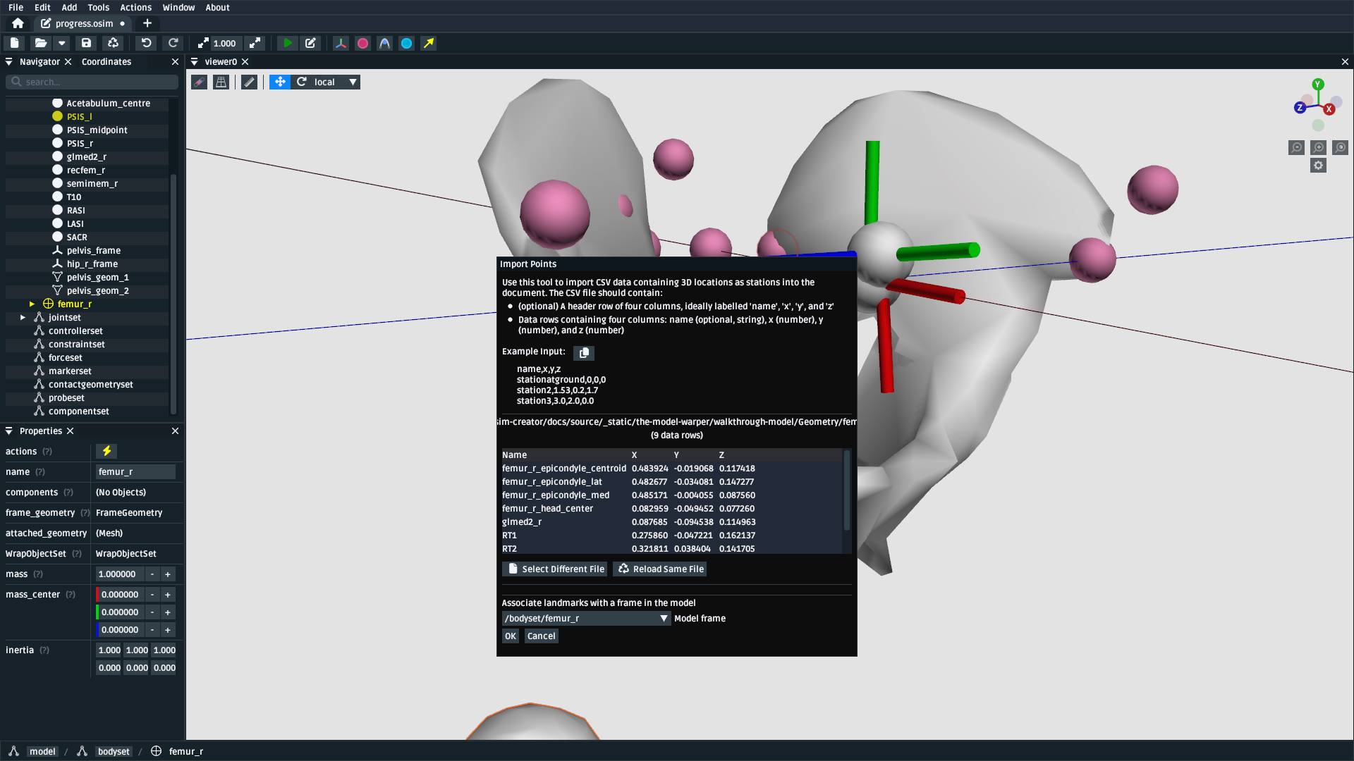
Fig. 8.13 The Import Points dialog, with femur_r.landmarks.csv. Make sure to
select femur_r as the body to attach the landmarks to. Otherwise, they will end up
attached to ground.#
8.13. Add a StationDefinedFrame on femur_r for the Hip Joint#
This process is exactly the same as Add a StationDefinedFrame on pelvis for the Pelvis Frame, but we are now defining
how the femur attaches to the hip by defining a frame on femur_r based on
the landmarks attached to it:
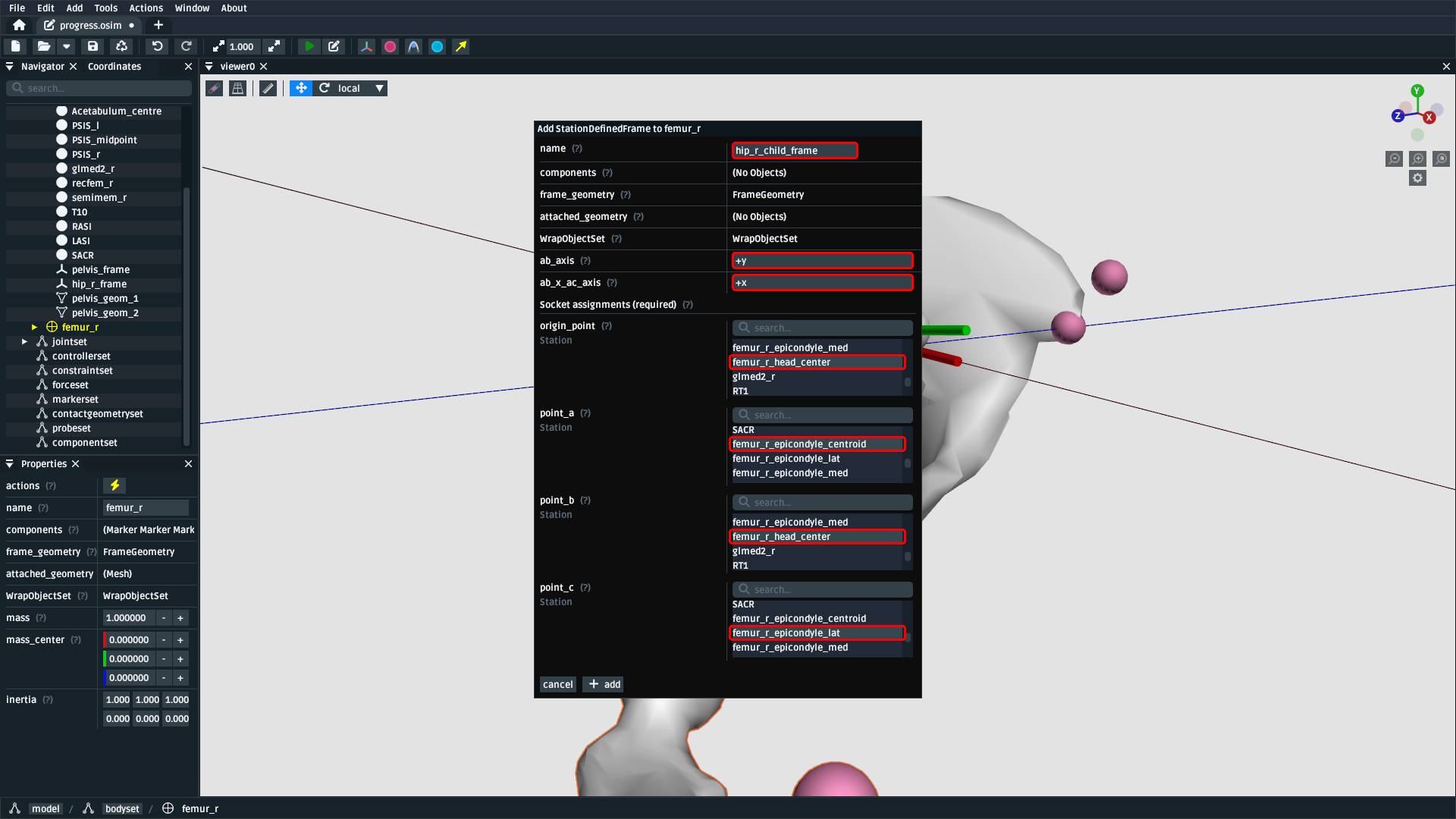
Fig. 8.14 Right-click the femur_r body and add a StationDefinedFrame. Call it
hip_r_child_frame, make femur_r_head_centre the origin_point and
point_b, femur_r_epicondyle_centroid point_a, and femur_r_epicondyle_lat
point_c. Additionally, specify that ab_axis is +y and
ab_x_ac_axis is +x.#
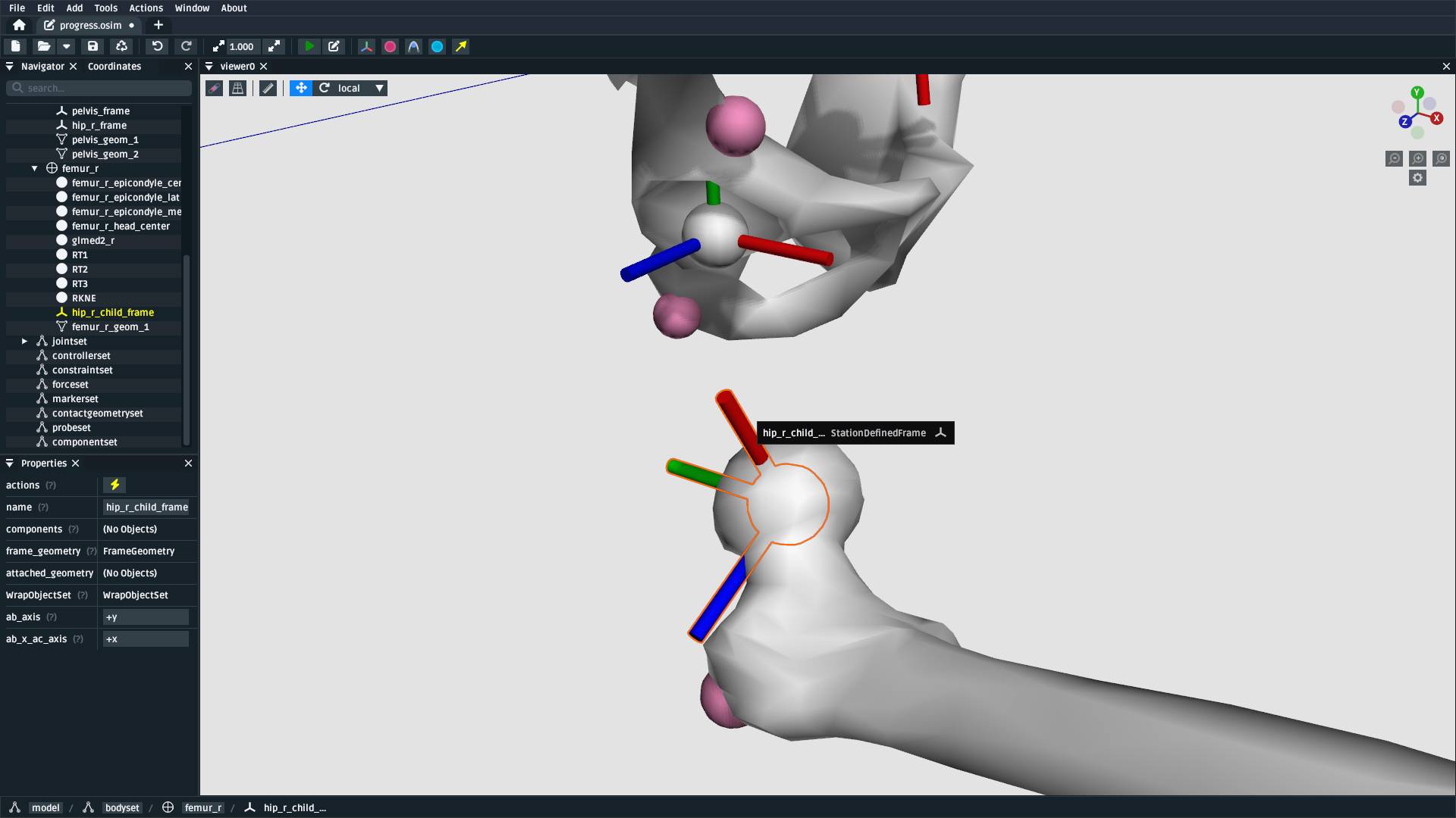
Fig. 8.15 The relationship between the landmarks defines the hip joint’s child frame
on femur_r, which lets us join them together in the next step.#
8.14. Reassign hip_r’s Child Frame to the StationDefinedFrame#
This process is exactly the same as Reassign pelvis_to_ground to the StationDefinedFrame, but we
now make the hip joint join hip_r_frame (parent) to the hip_r_child_frame
(child) we just created:
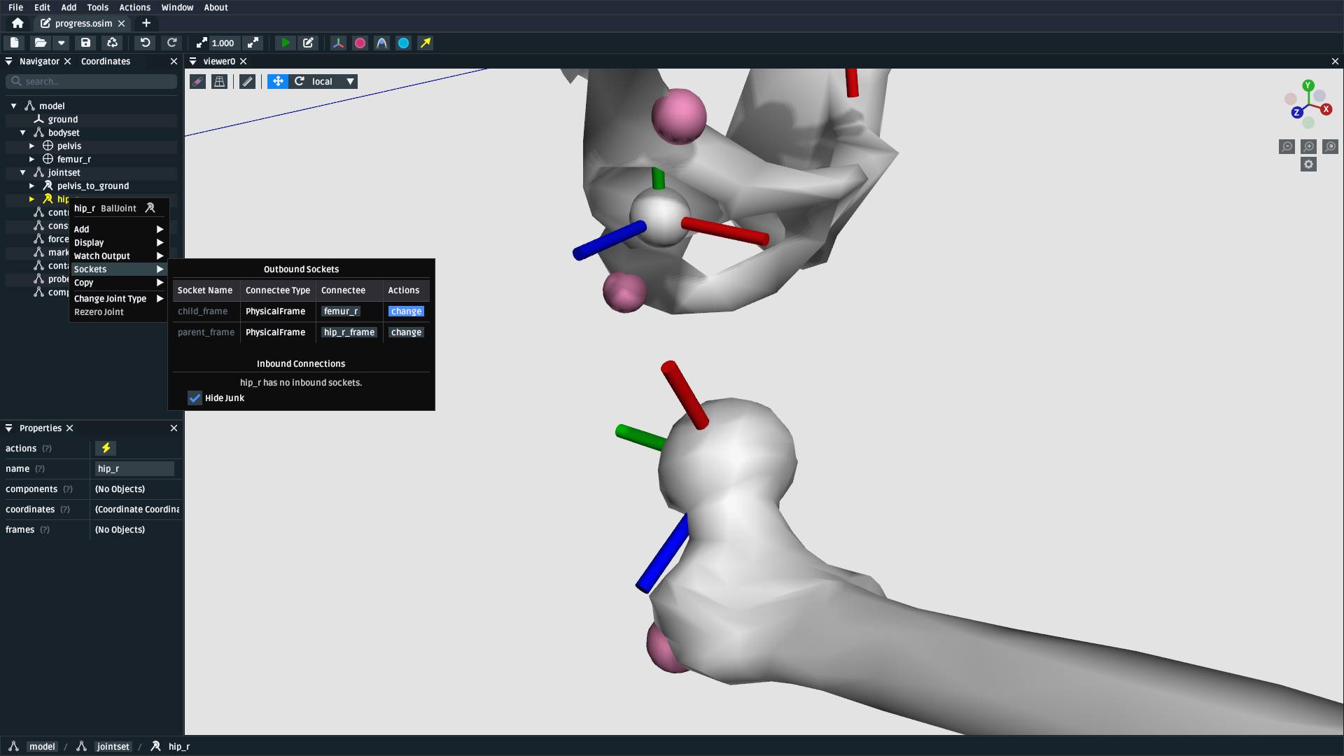
Fig. 8.16 Use the Navigator panel to find and right-click the hip joint (jointset/hip_r),
then find child_frame in the Sockets menu and change it to the
StationDefinedFrame created in the previous step (/bodyset/femur_r/hip_r_child_frame).#
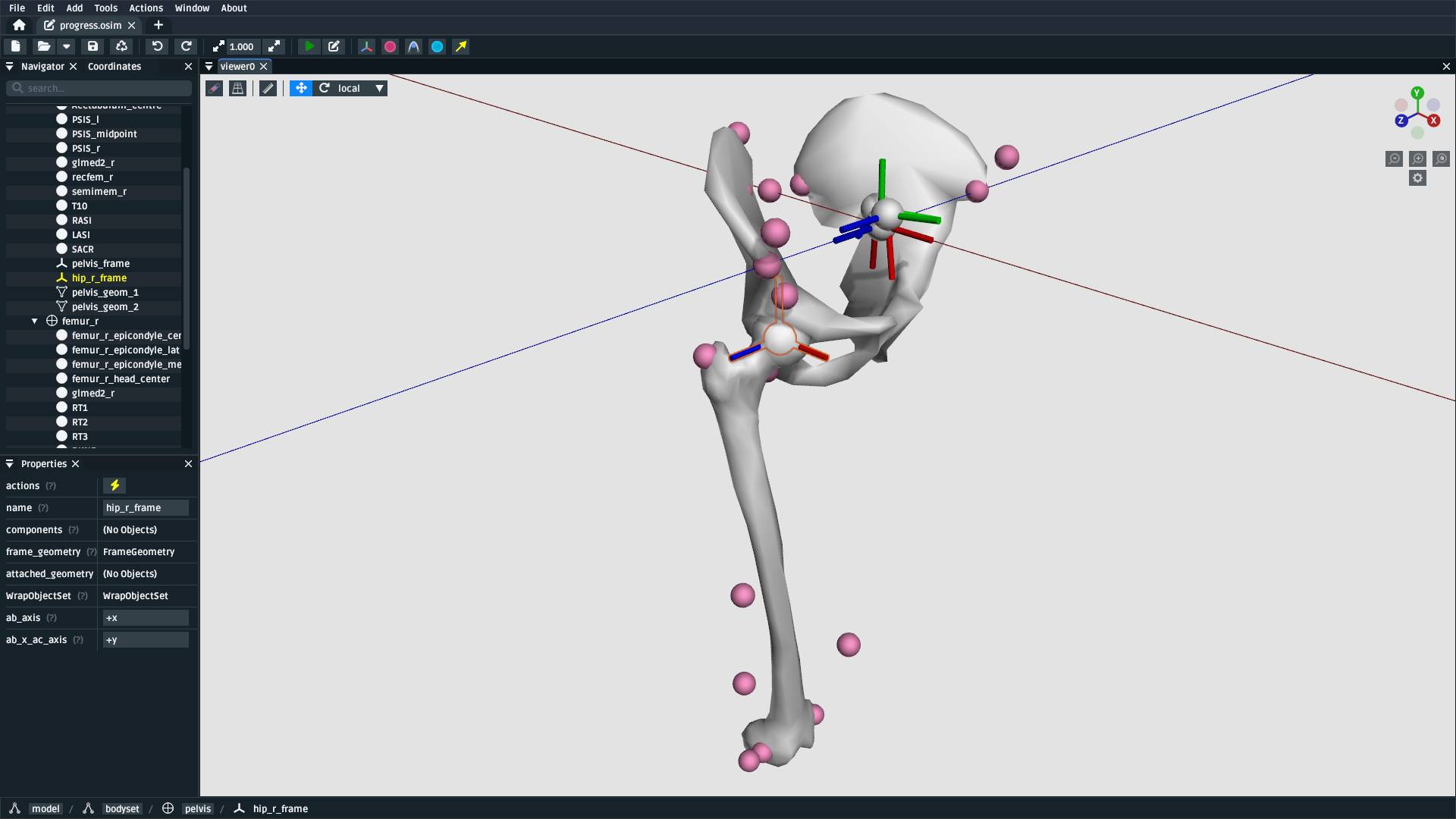
Fig. 8.17 After reassigning the hip joint to the StationDefinedFrames, the femur should
now be correctly transformed with respect to the pelvis.#
8.15. Add a StationDefinedFrame on femur_r for the Knee Joint#
For the knee joint, we can create another StationDefinedFrame on femur_r at the
epicondyle centroid. The steps are similar to Add a StationDefinedFrame on femur_r for the Hip Joint but, this time, we define
the origin_point as the femur_r_epicondyle_centroid landmark instead of
the femur_r_head_centre.
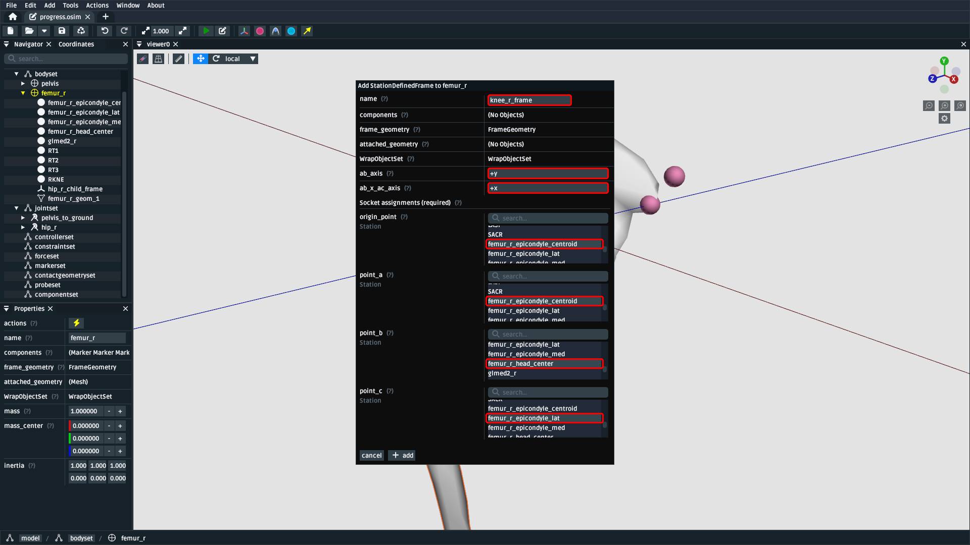
Fig. 8.18 Right-click the femur_r body and add a StationDefinedFrame. Call it
knee_r_frame, make the femur_r_epicondyle_centroid the frame
origin_point and point_a, femur_r_head_centre point_b, and
femur_r_epicondyle_lat point_c. Additionally, specify that ab_axis
is +y and ab_x_ac_axis is +x.#
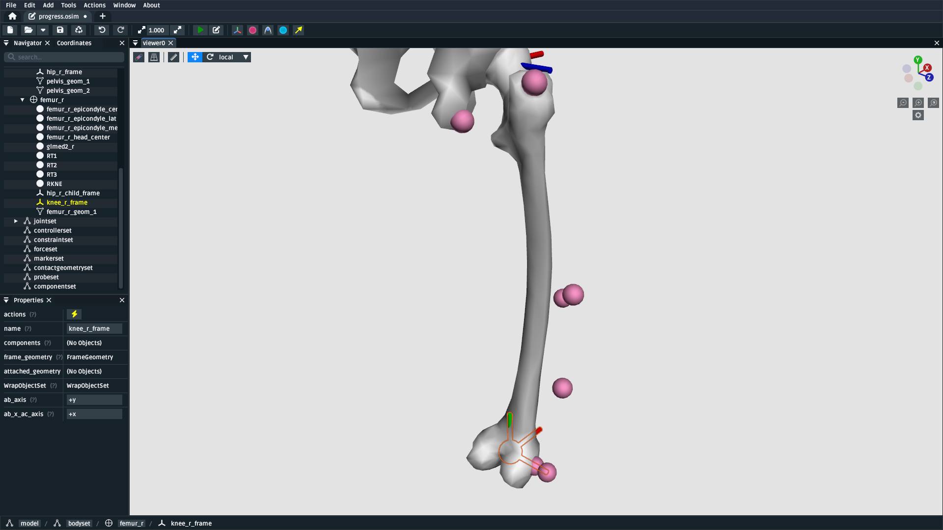
Fig. 8.19 The relationship between these landmarks specifies the knee’s coordinate system. Once added, you
should be able to see the StationDefinedFrame in the model. This is the “parent” half of the
knee joint definition in OpenSim.#
8.16. Add a Tibia Body#
Note
To reduce repetition, we have provided tibia_r.vtp and tibia_r.landmarks.csv in an
already-knee-joint-centered coordinate system. If they were in the same coordinate
system as the femur and pelvis, we would similarly need to define a StationDefinedFrame
for the knee on the tibia.
Similar to Add a Femur Body, add a tibia body with the tibia mesh (tibia_r.vtp)
attached to it to the model. For this model, use the following parameters:
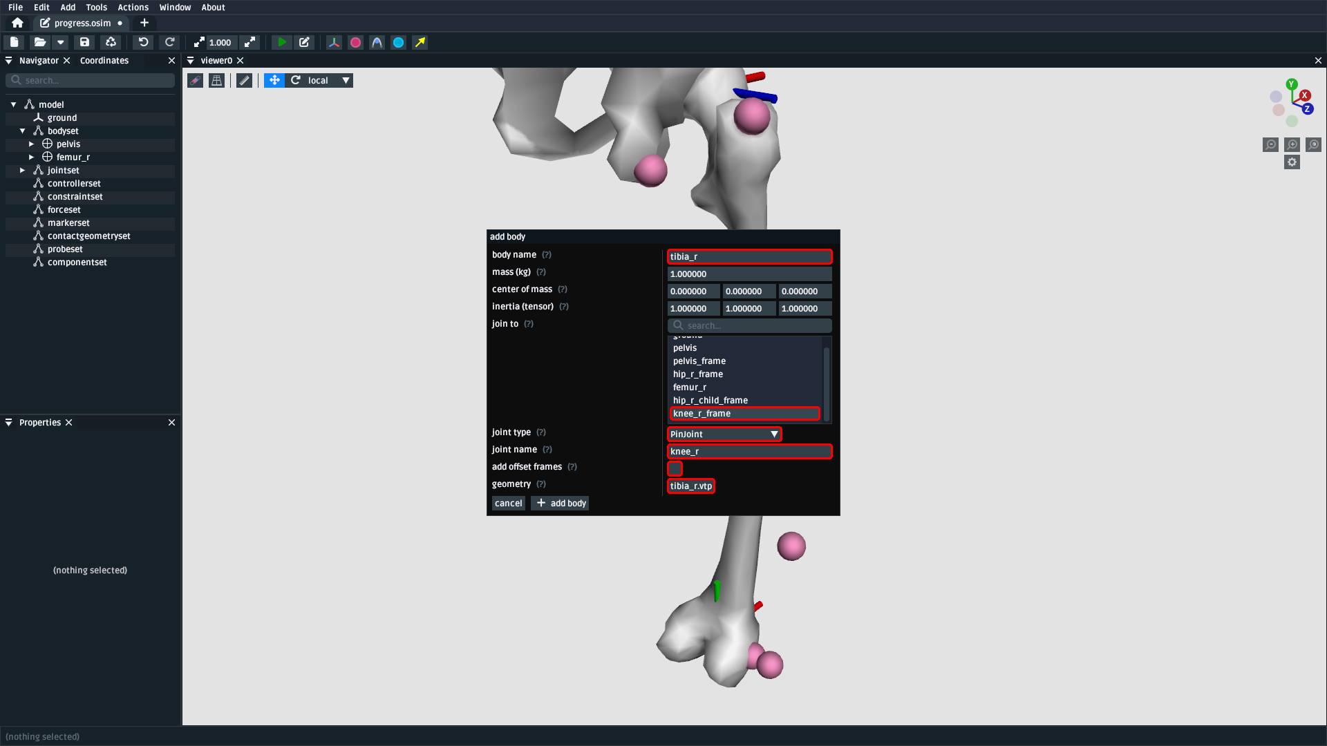
Fig. 8.20 Add the tibia body to the model with these properties. Make sure to attach the
tibia_r.vtp mesh to the body.#
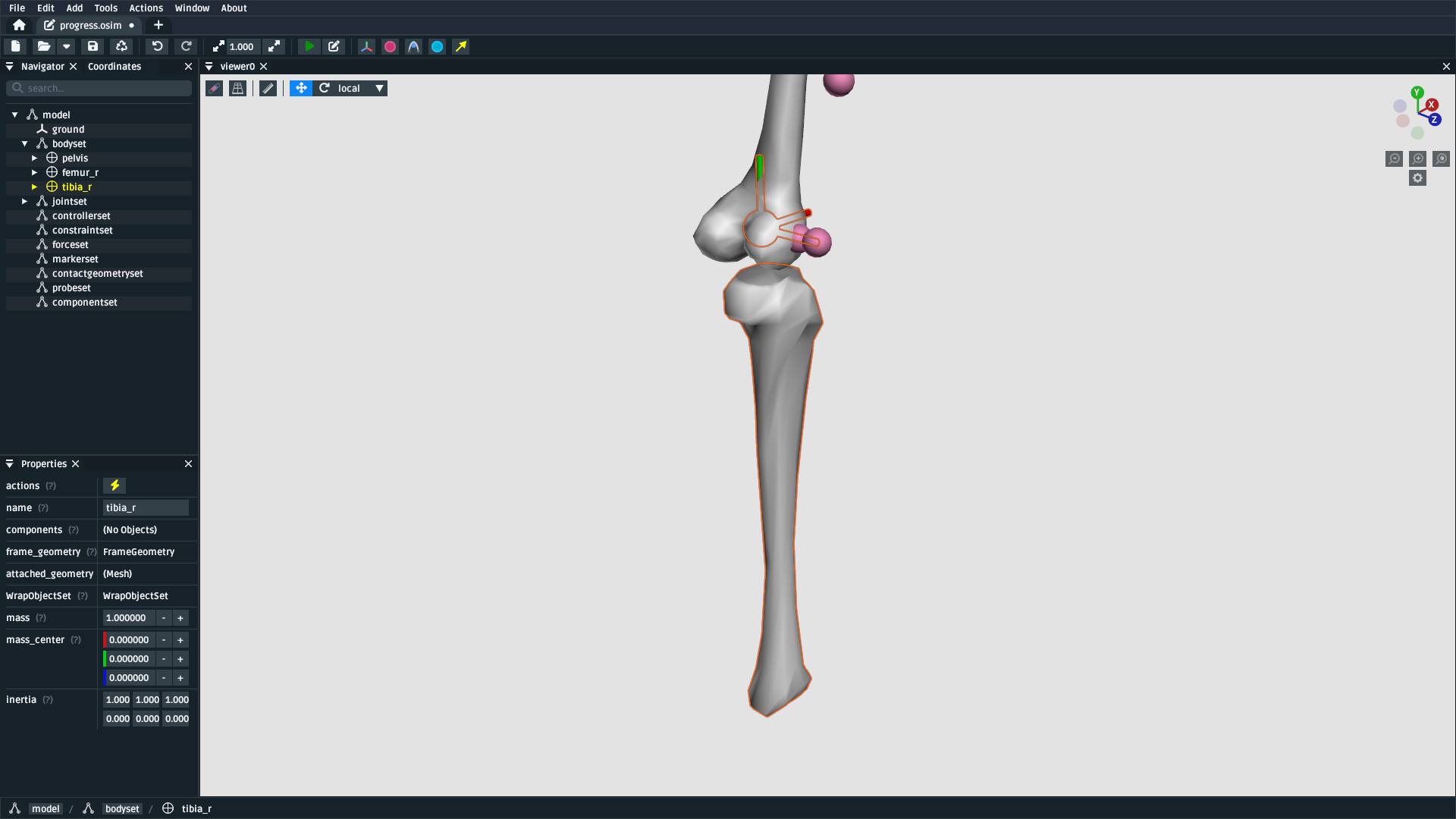
Fig. 8.21 To save some time, the provided tibia mesh data (tibia_r.vtp) is already defined
with respect to the knee origin, which means that we do not need to define a
StationDefinedFrame for the tibia. (available in supplied resources as
make-a-lower-leg_after-adding-bodies-and-joints.osim).#
8.17. Import Tibia Landmarks#
This process is exactly the same as Import Pelvis Landmarks, but we are now
importing tibia_r.landmarks.csv and attaching them to the tibia_r in preparation
for using them as muscle points and markers later on:
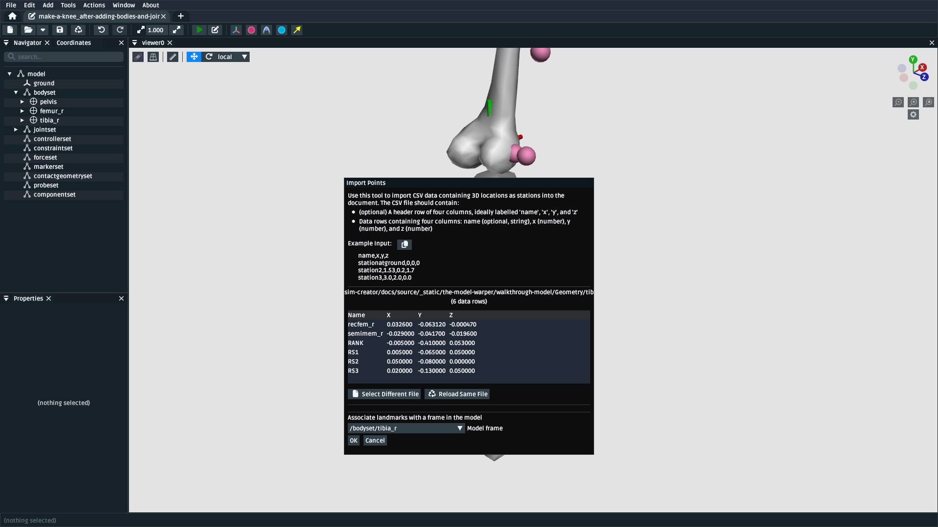
Fig. 8.22 The Import Points dialog, with tibia_r.landmarks.csv. Make sure to
select tibia_r as the body to attach the landmarks to. Otherwise, they will end up
attached to ground.#
8.18. Add Muscles#
Now that all bodies have been added and joined together, we can define muscles that emit forces on those bodies.
The .landmarks.csv files imported in previous steps also include muscle points, which
we can use to define three muscles. Right-click somewhere in the scene and use the Add menu
(or alternatively, use the Add menu at the top) to add Millard2012EquilibriumMuscles with
the following names and muscle points:

Fig. 8.23 Create a Millard2012EquilibriumMuscle called glmed_r with glmed_r_p1
and glmed_r_p2 as path points.#
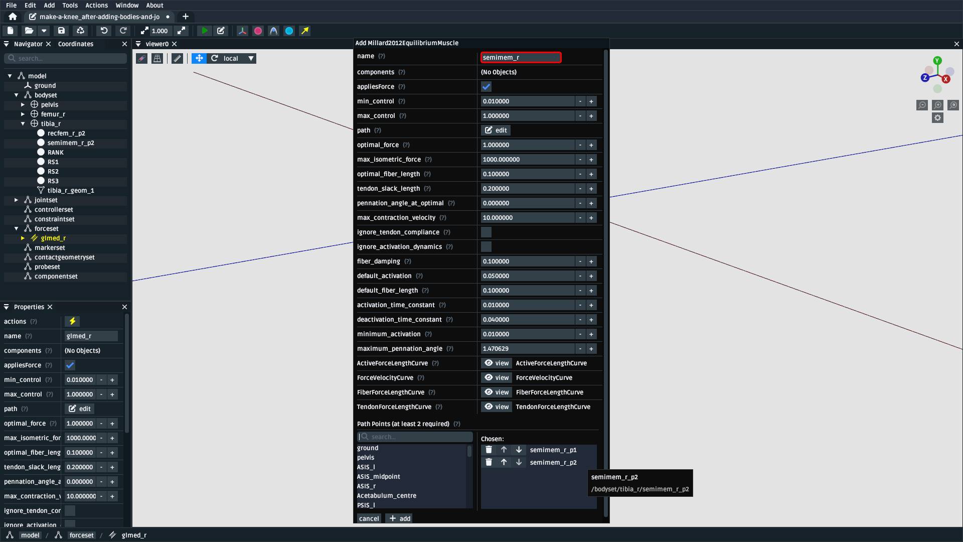
Fig. 8.24 Create a Millard2012EquilibriumMuscle called semimem_r with semimem_r_p1
and semimem_r_p2 as path points.#
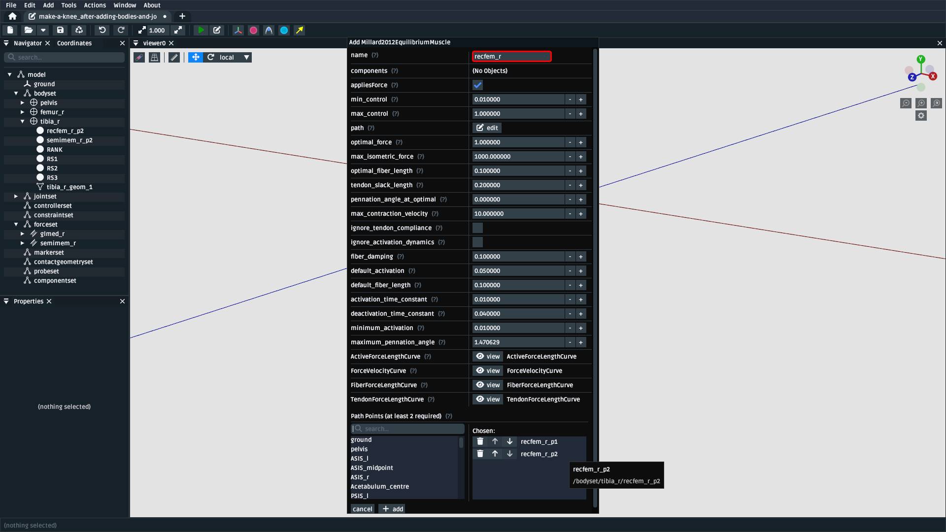
Fig. 8.25 Create a Millard2012EquilibriumMuscle called recfem_r with recfem_r_p1
and recfem_r_p2 as path points.#
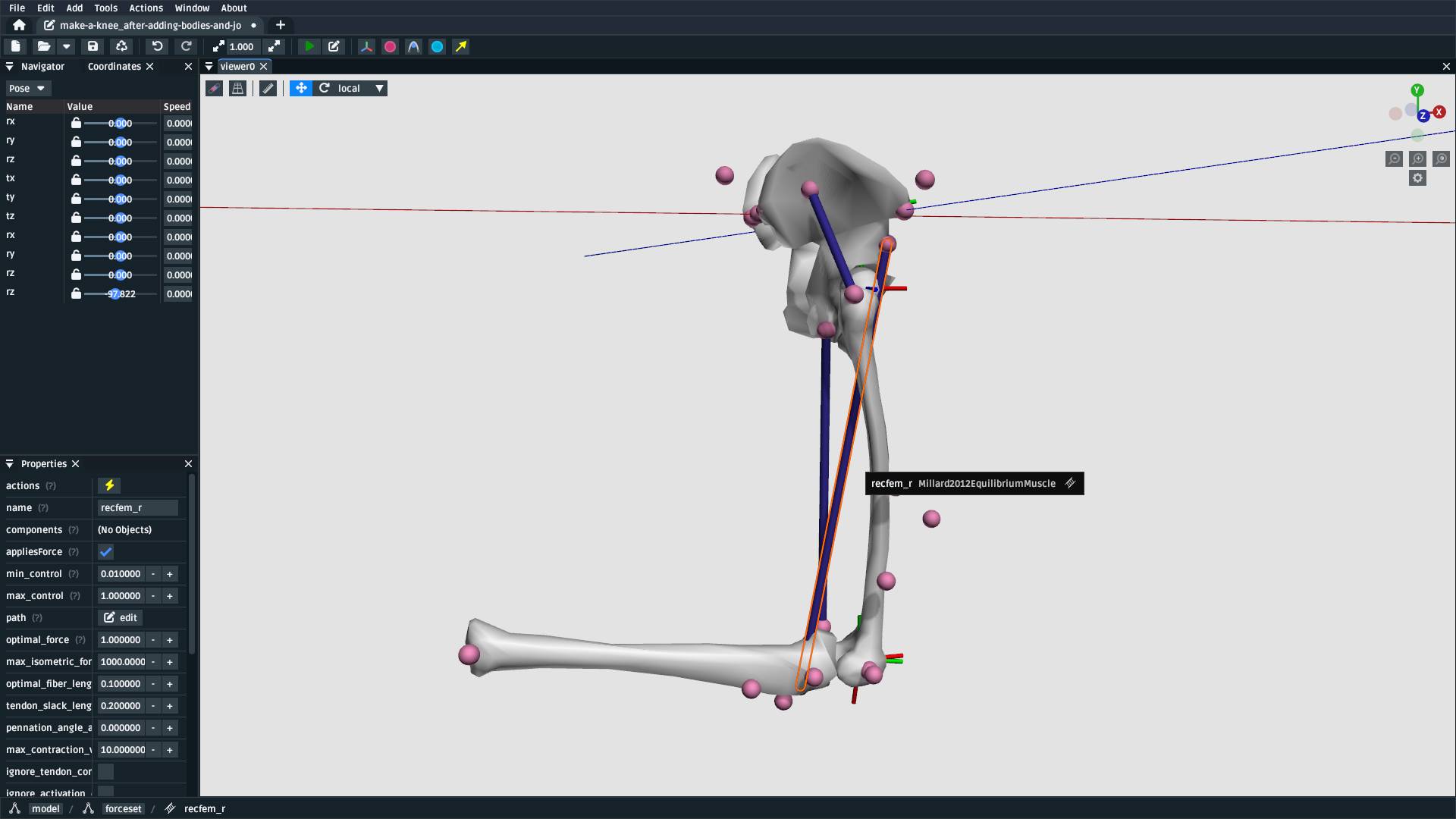
Fig. 8.26 The model after adding the muscles and flexing by approximately 90
degrees. As can be seen, recfem_r will clip through the knee. This
is fixed with wrapping, which is described in the next section.#
8.19. Add a Knee Wrap Cylinder Wrap Surface#
Now that muscles have been added to the model, you’ll see a problem: recfem_r clips
through the femur (Fig. 8.26)! This is because
we haven’t told OpenSim how the muscle should wrap around things. To do that,
we need to add a wrapping cylinder that approximates the shape of the knee:
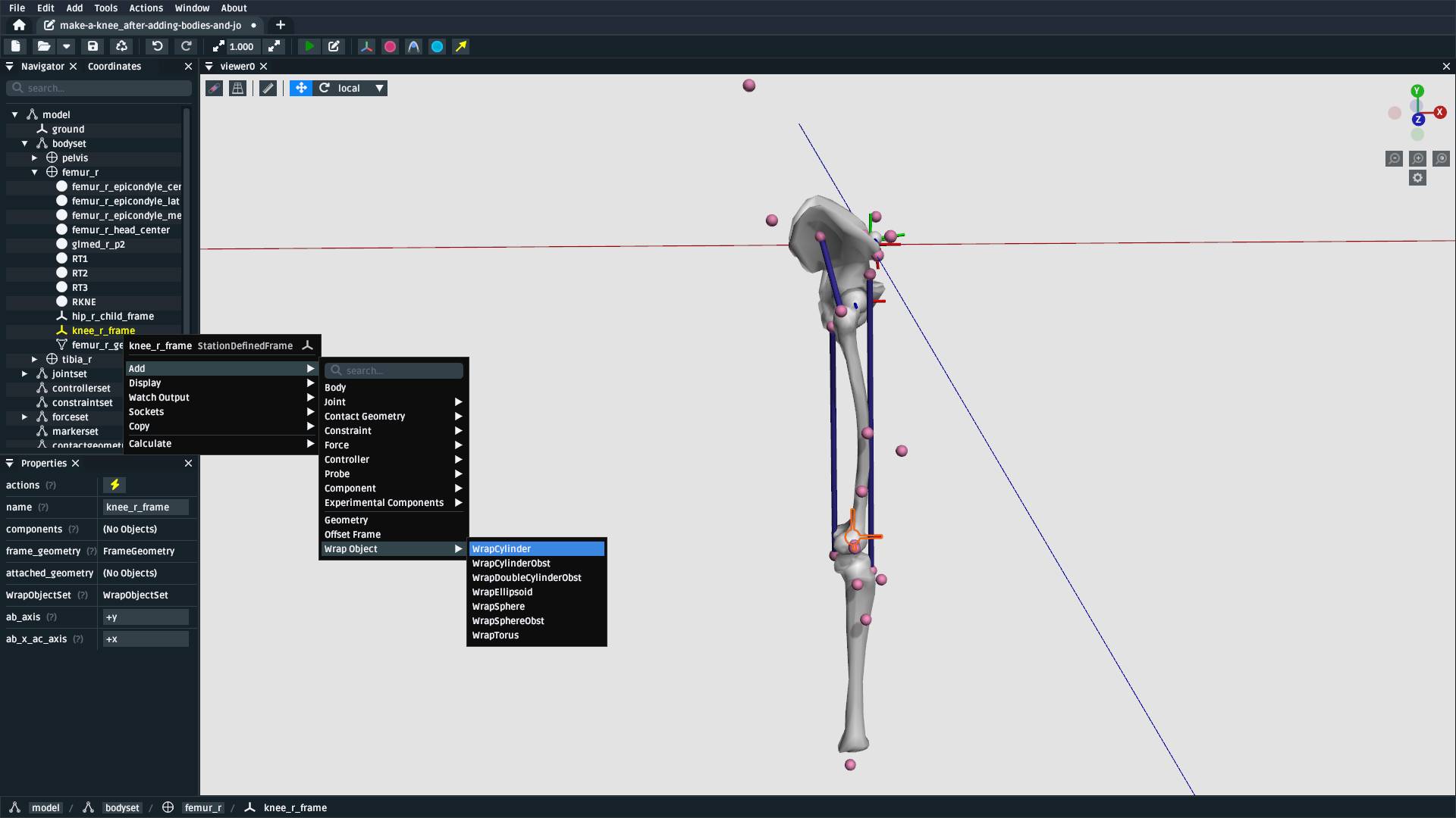
Fig. 8.27 Right-click the knee_frame StationDefinedFrame and then Add > Wrap Object > WrapCylinder
to add a wrap cylinder to the knee. Warning: it will initially be very
large (1 m radius).#
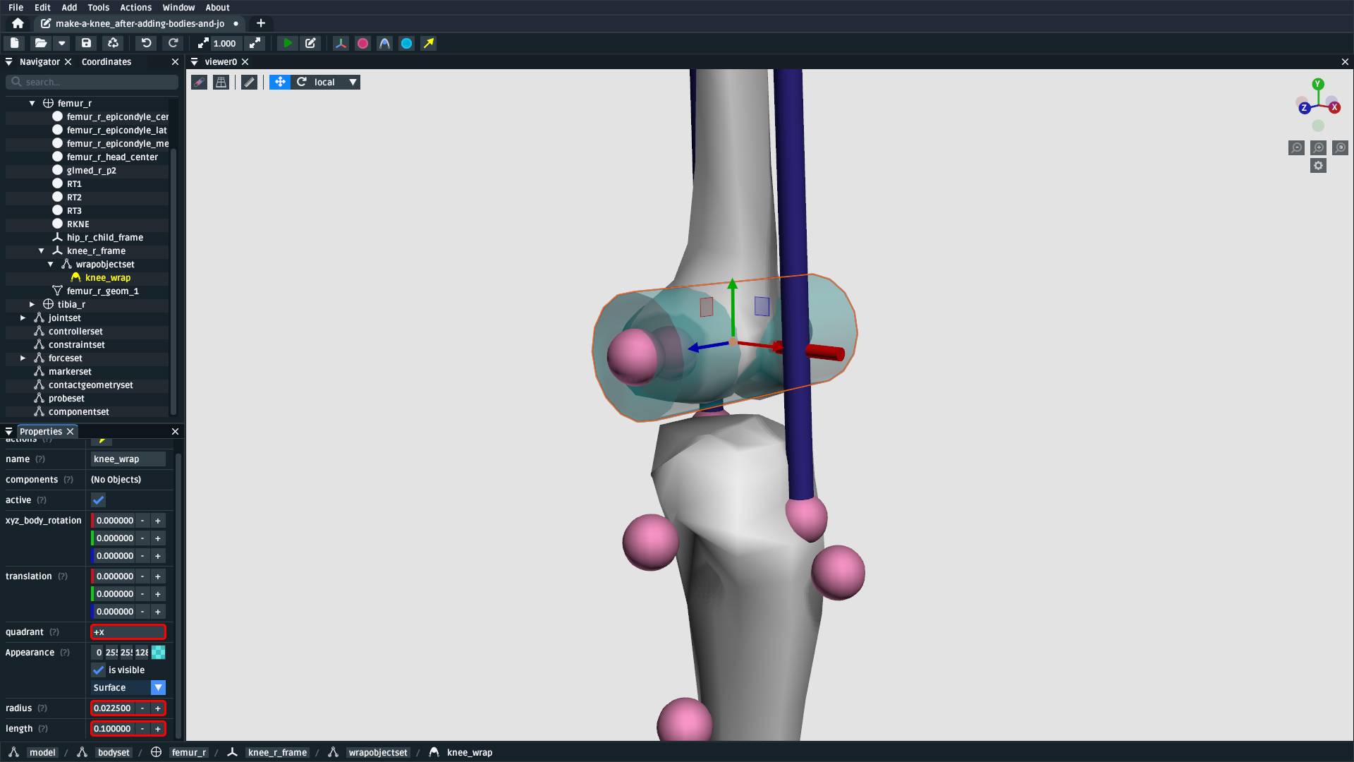
Fig. 8.28 Using the properties panel, rename the wrap cylinder to knee_wrap, give
it a quadrant of +x (so that muscles always wrap over its X
quadrant), a radius of 0.0225, and a length of 0.1, so that
is somewhat matches the shape of the knee. recfem_r muscle won’t wrap
over the cylinder yet. That’s handled in the next step.#
8.20. Associate the Muscle with the Wrap Surface#
Once knee_wrap has been added, you may notice that recfem the isn’t wrapping
over it yet. This is because OpenSim uses “Path Wrap”s to describe which wrap objects
are associated with each muscle in the model.
To create this association, you can right-click a muscle and add a path wrap:
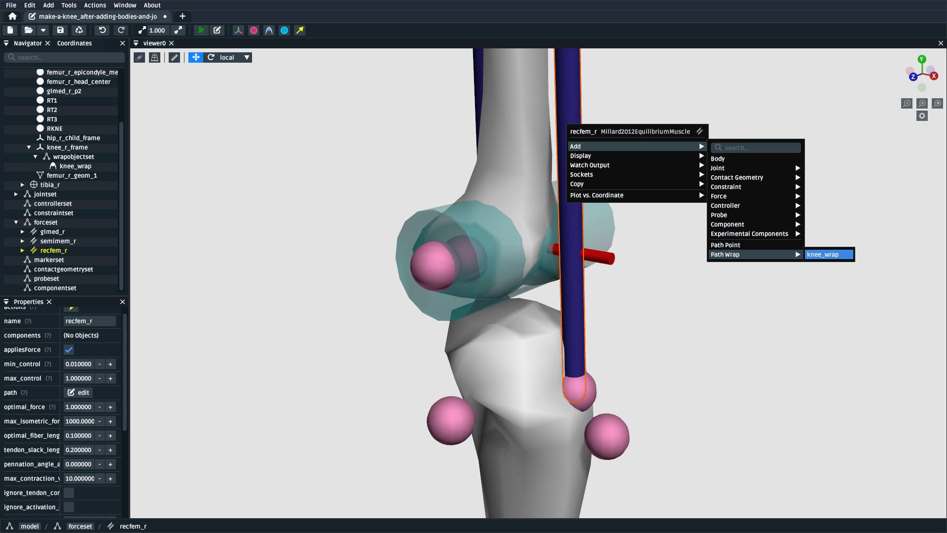
Fig. 8.29 Use recfem_r’s context menu to Add a Path Wrap association with the
knee_wrap WrapCylinder.#
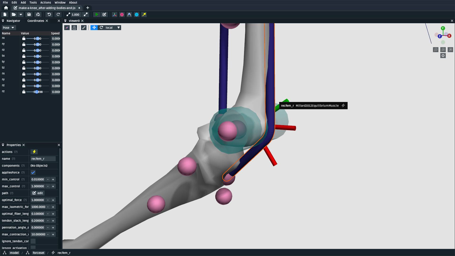
Fig. 8.30 After adding the path wrap, the muscle should now correctly wrap over the X quadrant
of the WrapCylinder, which more closely mimics how an anatomically-correct muscle
would wrap over the knee.#
8.21. Minimal Modelling Steps Complete!#
At this point in the tutorial, we have completed some of the most crucial model building steps: adding bodies, joining them, and adding muscle paths. This doesn’t mean the model is production ready—for example, we still have to handle body masses, body centers of mass, inertia, and muscle parameters—but these initial components act as a suitable canvas that can be refined into the final model:
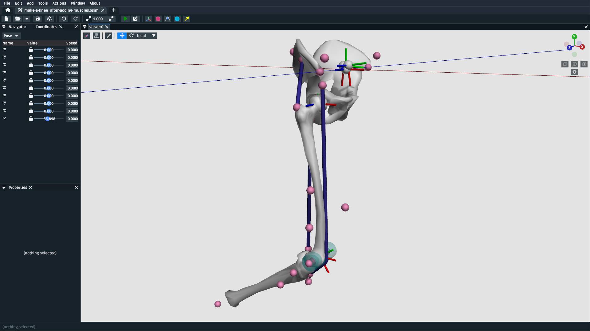
Fig. 8.31 The model after adding bodies, joints, and muscle paths (available in supplied
resources as make-a-lower-leg_after-adding-muscles.osim).#
8.22. Optional: Clean up the Model#
The model we have created is functional, but would benefit from a few cleanups to make it easier to work with (especially for when we use it in The Model Warper). The cleanup steps are described below.
8.22.1. Delete Markers Used to Define Muscles#
When we imported points (above), it included muscle attachment points. The muscles
created from those attachment point Markers are independent of them, so we can
safely delete them.
To delete the markers, select each of the following markers in the model and press Delete or
Backspace (you can search for them by name in the navigator panel): recfem_r_p1,
recfem_r_p2, semimem_r_p1, semimem_r_p2, glmed_r_p1, glmed_r_p2.
8.22.2. Rename and Define Correct Ranges for the Joint Coordinates#
The pelvis_to_ground, hip_r, and knee_r joints we added are controlled by
coordinates, but those coordinates have generic default names like rx and tx. Additionally,
they have unrealistic ranges, which allows (e.g.) the knee to flex >360 degrees.
To make the model’s joint coordinates more realistic, rename and re-range them. This can be done by finding the coordinate under the applicable joint in the navigator panel, left-clicking it, and then editing it via the properties panel. Here are the names and ranges we used:
Joint |
Original Coordinate Name |
New Coordinate Name |
New Range |
|---|---|---|---|
|
|
|
(unchanged) |
|
|
|
(unchanged) |
|
|
|
(unchanged) |
|
|
|
(unchanged) |
|
|
|
(unchanged) |
|
|
|
(unchanged) |
|
|
|
-0.9 to 0.5 |
|
|
|
-0.7 to 0.7 |
|
|
|
-0.6 to 2.1 |
|
|
|
0 to 2.1 |
8.22.3. Make Mesh Paths Relative#
When OpenSim Creator attaches meshes to frames/bodies, it uses an absolute filepath
(e.g. C:\Data\project\mesh.obj). It does this because the model may not have an
on-disk location during editing (e.g. it’s in memory and not saved yet), or it may be
saved somewhere else.
To fix this, once you know where your model will be saved, ensure all meshes are in
a directory next to the model file called Geometry. Then you can click on each
mesh in the model and use the properties panel to change the mesh_file property to
just be the filename (e.g. C:\Data\model\Geometry\mesh.obj becomes mesh.obj).
OpenSim knows to check for mesh files in the Geometry subdirectory.
8.22.4. Move Experimental Markers into /markerset#
When we imported points (above), it included experimental markers for use in IK. These
should remain in the model, but be moved into the model’s /markerset, because while
it’s technically valid for them to be anywhere in the model, other tools
in the OpenSim ecosystem (e.g. OpenSim GUI’s scale tool) will only
recognize markers that are specifically in the /markerset collection.
To move a marker’s data (not it’s location or attachment) to /markerset, right-click
the marker and then use Move To > /markerset. Perform this procedure on the following
markers:
pelvismarkers:T10,RASI,LASI,SACRfemur_rmarkers:RT1,RT2,RT3,RKNEtibia_rmarkers:RANK,RS1,RS2,RS3
8.22.5. Bake StationDefinedFrames#
Warning
This is only necessary if the model needs to be compatible with
OpenSim <4.6, because earlier versions of OpenSim do not natively
support StationDefinedFrame components.
The final model download does not include the application of
this step, because StationDefinedFrames are crucial when
performing non-linear scaling steps (as in The Model Warper).
If backwards compatibility is required, then there is an experimental one-off
operation for converting all StationDefinedFrames in a model into traditional
PhysicalOffsetFrames. In the main menu of the model editor, go to
Tools > Experimental Tools > WIP: Bake Station Defined Frames. This should
replace all StationDefinedFrames in the model with an equivalent
PhysicalOffsetFrame.
8.23. Final Model#
Here is a picture and of the final model with the clean-ups applied (apart from baking StationDefinedFrames),
it is available in the supplied resources (see Download Resources) as
make-a-lower-leg_final.osim:
Fig. 8.32 The final model, with various clean-ups applied to ensure that it has
easy-to-understand coordinate names and good compatibility with other
tools in the ecosystem. Available as make-a-lower-leg_final.osim in the
available resources (see: Download Resources).#
8.24. Summary#
This tutorial was a brief overview of some of the available techniques for building a biological model using OpenSim Creator’s model editor workflow. The key points are:
It’s possible to import/export 3D point data from/to CSV files, which can be handy when using external scripts/tools.
You can use
StationDefinedFrames to define frames based on anatomical landmarks. How they work is explained in more detail in Station Defined Frames.StationDefinedFramesame have the advantage that they are usable with warping algorithms that operate on points (see The Mesh Warper and The Model Warper).There’s a few ways to add muscles to a model. Muscles can be created from at least two other locations in the model. This means that you can import/place those points before creating the muscle. Alternatively, you can create a dummy muscle and edit the path later on.
Wrap geometry is crucial when designing muscle paths that wrap over geometry like bones. Wrapping is usually a two-step process (add the wrap geometry, associate the geometry with a path).
8.25. Next Steps#
Once you have a model, you will probably want to start using it with the rest of the OpenSim ecosystem. For example, you can now use it with the analysis tools in OpenSim GUI.
If you want to re-use this model with multiple subjects, then scaling or warping of the model is required. OpenSim Creator’s solution to this is The Model Warper, which uses the model created in this tutorial as an input.