
1. Make a Pendulum#
In this first tutorial, we will be making a conventional pendulum using OpenSim Creator:
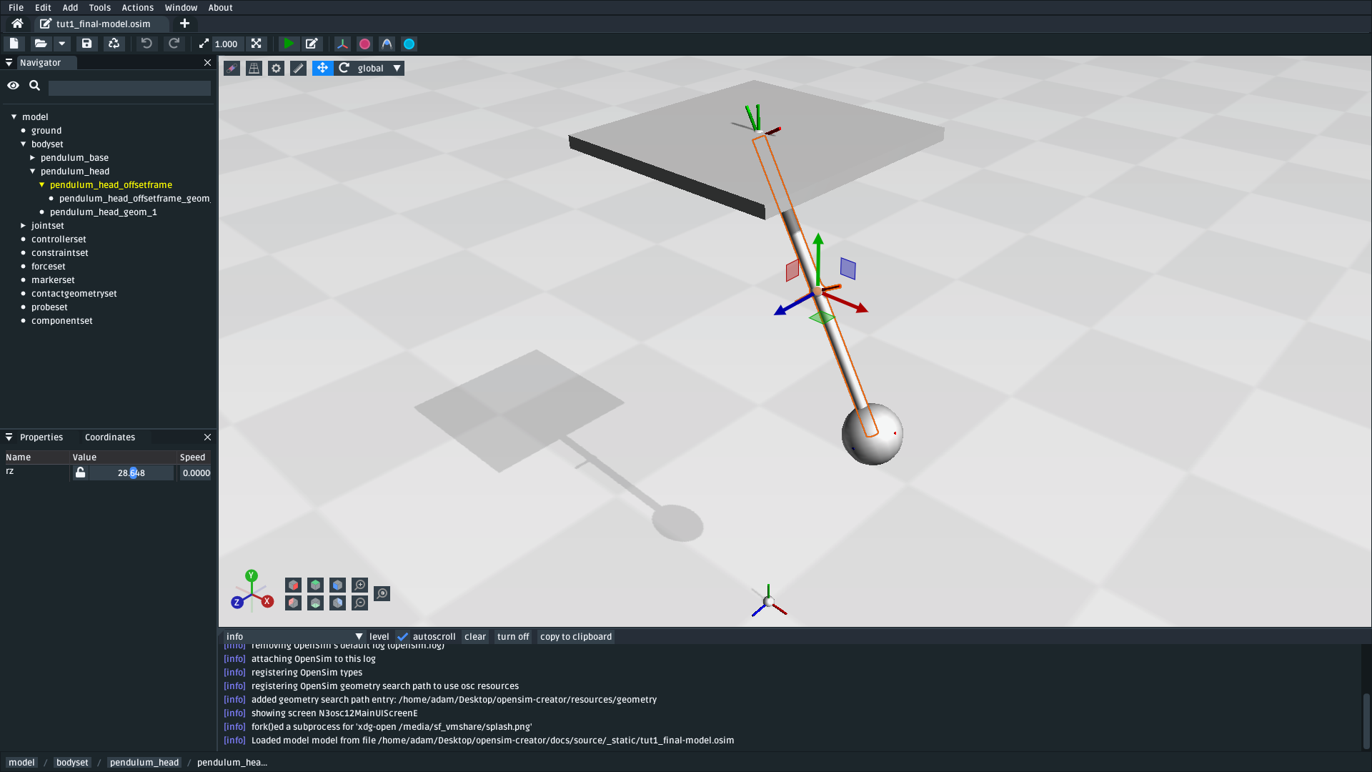
Fig. 1.1 The pendulum created by this tutorial. Although OpenSim is commonly associated with biomechanical simulations, it can also be used to simulate “conventional” rigid-body models (download model).#
OpenSim is based on Simbody, a physics library for science- and engineering-quality simulations of articulated mechanisms. This means that OpenSim Creator can be used to simulate things like pendulums, robots, and biomechanical systems. This tutorial focuses on creating a pendulum–one of the simplest physical systems–because it introduces core concepts that are common to all kinds of models.
1.1. Prerequisites#
This is a beginner-level introduction. The only thing you need to ensure is that you have followed the Getting Started steps.
1.2. Topics Covered by this Tutorial#
Creating a basic OpenSim model containing bodies, joints, and decorative geometry
Coordinate systems in OpenSim
OpenSim model topology
(optional) Decorating the model to resemble what it’s modelling
1.3. Create a New Model#
In OpenSim Creator, create a new model. You can create a new model by clicking “New Model” in the home screen, or pressing Ctrl+N. It should create a blank model that looks like this:
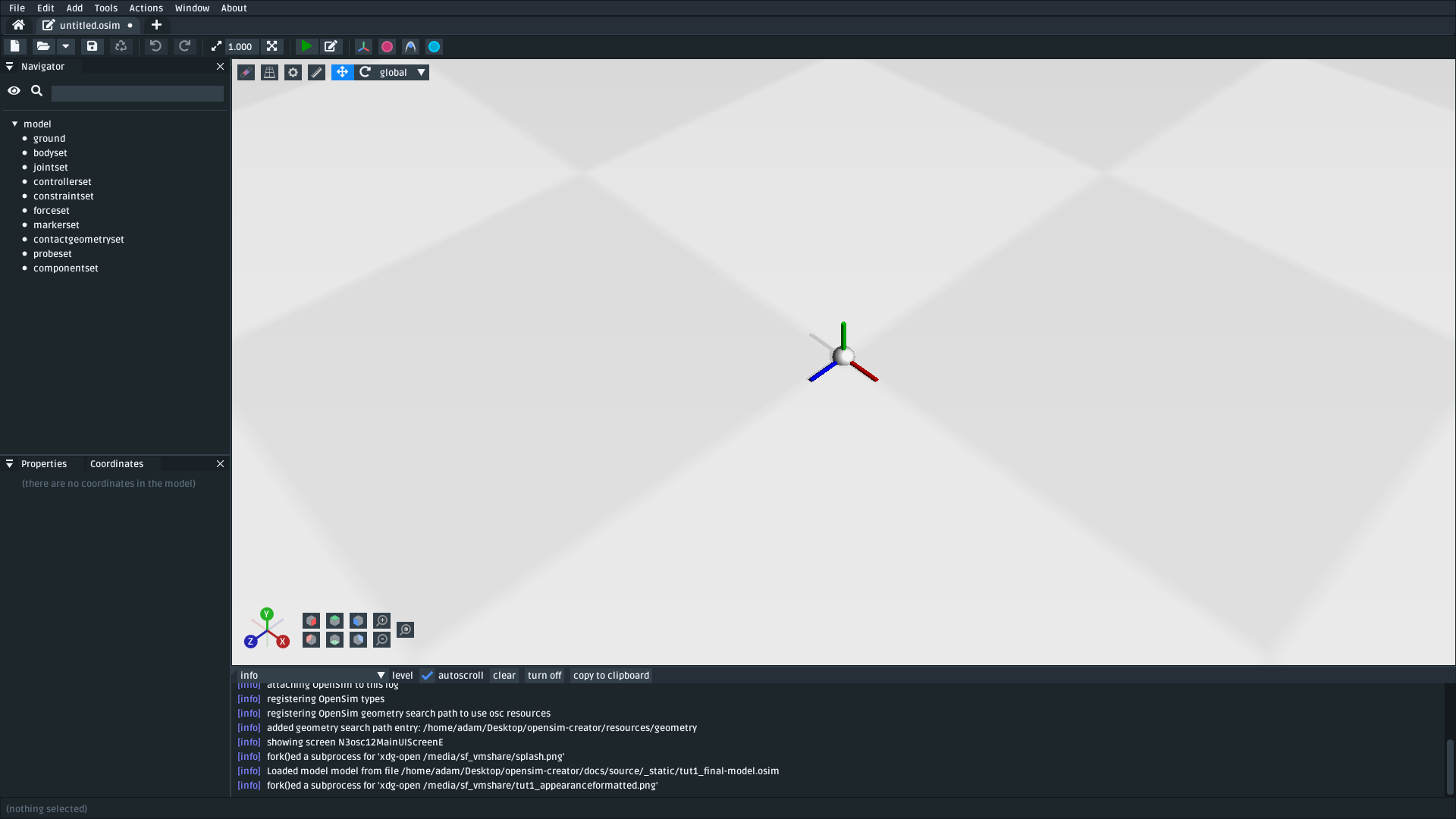
Fig. 1.2 A blank OpenSim model, with the ground frame shown in the middle. When shown, frames within a model are color-coded with red, green, and blue, which indicate X, Y, and Z respectively.#
You should see a 3D viewer with a chequered floor and a set of axes in the middle. These axes are called frames in OpenSim. Frames express the position and orientation of something in the model. In this case, they are showing the position and orientation of the model’s ground. The ground frame of a model is always located at (0, 0, 0) and is always aligned along the world’s axes. This means that the red, green, and blue axes of the ground frame correspond to the +X, +Y, and +Z of the world.
Note
OpenSim models are described using a relative coordinate system. This means that the position and orientation of each component (e.g. a body) in an OpenSim model is described relative to some other component in the model.
This has practical implications. For example, setting a component’s translation to +1 in X does not mean that the component will be positioned at (1, 0, 0) in the scene. The component may be positioned at parent.position + parent.orientation*(1, 0, 0), or at some other location, depending on what (and how) the component is attached to the other components in the model (the model’s topology). This relative, topology-sensitive, approach is in contrast to artistic modelling software (e.g. Blender), where scene elements are typically transformed independently and relative to the world.
The only component that doesn’t use relative coordinates is the ground. The ground is always the “root” of the model’s connectivity graph and is always defined to be at, and aligned with, the origin of the world - (0, 0, 0). All other components within the model attach to ground directly or indirectly (i.e. via other components, such as joints).
1.4. Add a Body with a WeldJoint#
In the UI, open the Add menu at the top, or right-click an empty part of the 3D scene and open the Add menu, followed by clicking the Body button.
A dialog should pop up that prompts you to fill in the body’s details. Create a body with the following details:
Note
To use the Brick analytic geometry, use the Generated Geometry dropdown when selecting the geometry. This is better than
using a mesh file (e.g. brick.vtp) because the resulting model will not be dependent on the existence of the mesh file.
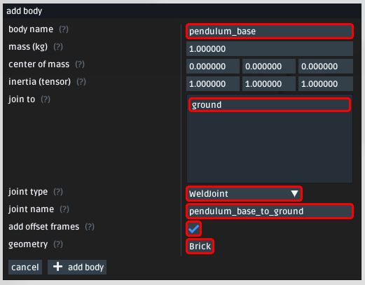
Fig. 1.3 Body properties for pendulum_base. Note: Make sure to use the same parameters, and to also attach a Brick generated geometry (highlighted).#
After adding pendulum_base, you should now see a cube in the 3D viewer. The cube is a decorative Brick geometry that you attached in the popup:
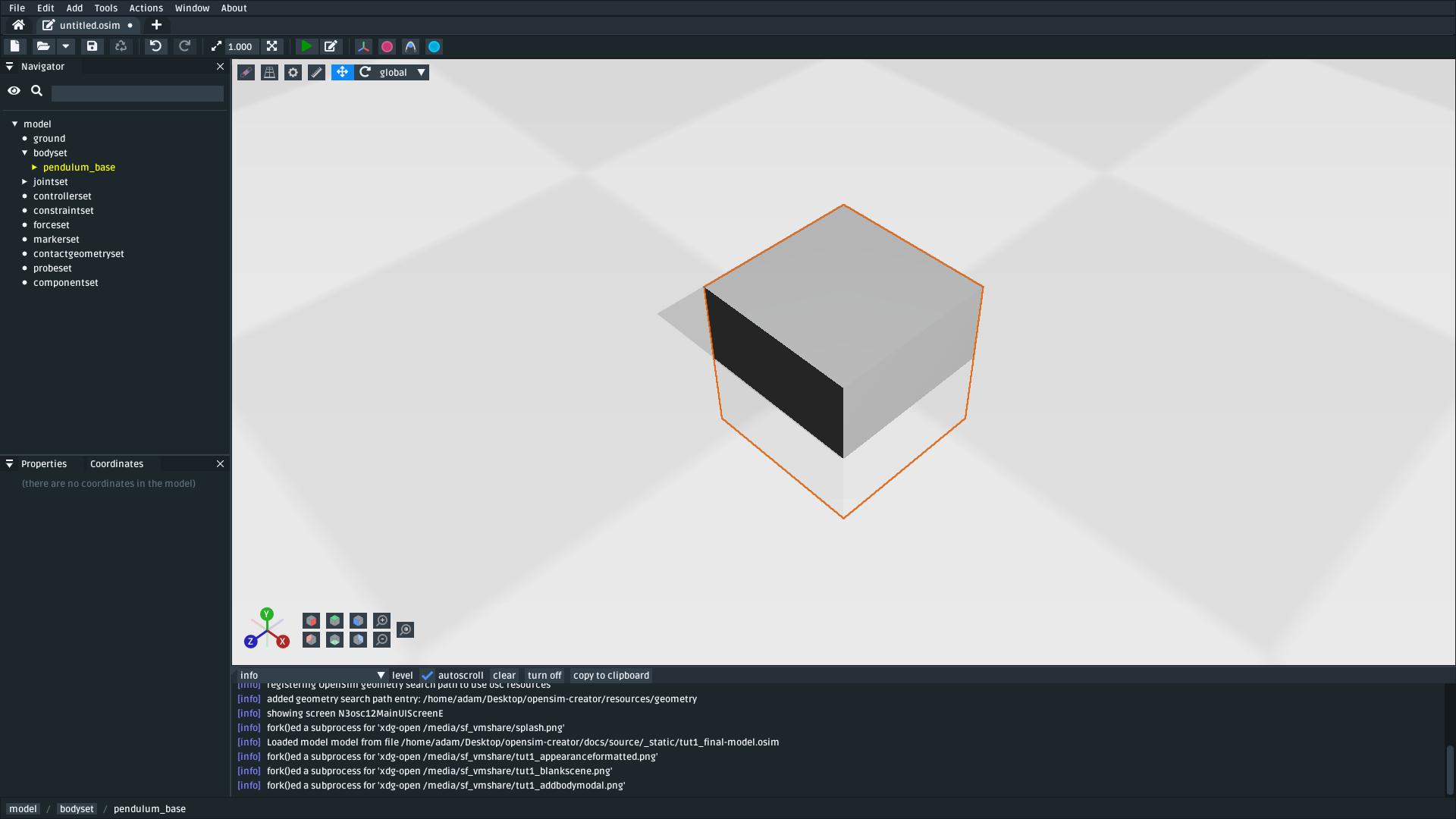
Fig. 1.4 The scene after adding pendulum_base into the scene with a Brick as its attached geometry. Although OpenSim models bodies as points, many OpenSim models also attach 3D geometry to the bodies to make the model to make it easier to visualize (download model).#
When we made pendulum_base, we ticked the add offset frames checkbox. Adding a body like this added four components into the model:
The body (
/bodyset/pendulum_base)A
WeldJoint(/jointset/pendulum_base_to_ground)An offset frame between the joint and the body (
/jointset/pendulum_base_to_ground/pendulum_base_offset)An offset frame between the joint and ground (
/jointset/pendulum_base_to_ground/ground_offset)
The body was added because we asked for it. The offset frames were added because they enable (effectively) moving the joint center later (by changing the offsets). However, why do we need a joint in the first place?
The reason we add joints is because bodies must be connected in a model topology to each other. That topology must ultimately connect to ground. This is because building an OpenSim model ultimately involves building a Kinematic Chain that the simulator (Simbody) understands.

Fig. 1.5 The logical topology of the model after adding pendulum_base into the scene. This topology dictates the relative coordinates and physical dynamics of those elements in the model. Here, pendulum_base is attached to ground via a WeldJoint. A WeldJoint has no degrees of freedom, so pendulum_base is effectively “anchored” in the scene.#
Note
OpenSim models are stored in a hierarchy. At the top of the hierarchy is the model, which contains child components (e.g. things like bodies and joints). Those components, in turn, may other child components–e.g. things like offset frames and decorative geometry.
Clicking something in OpenSim Creator typically selects the component you clicked on, so clicking the Brick in the 3D scene will select the Brick geometry that’s a child of the pendulum_base offset frame. You can use the navigator panel, or the component path in the status bar at the bottom of the UI, to see where the selected component is in the model’s hierarchy.
Components in an OpenSim model can also use sockets to form a graph-like connection to some other component. This enables components (which are stored hierarchically) to connect to each other in a non-hierarchical manner.
For example, bodies and joints are direct children of a model–they are, hierarchically speaking, siblings–but joints use sockets (parent_frame and child_frame) to connect to two frames/bodies and establish a joint topology graph (or kinematic chain).
When these tutorials write about the topology (or kinematics) of the model, they’re usually referring to how the various bodies, joints, and frames physically affect each other. That topology is usually dictated by the socket connectivity graph. By contrast, the model hierarchy, as shown in OpenSim Creator’s navigator panel, shows you the hierarchical storage of the model. Storage affects things like where the component’s data is ultimately saved in the resulting .osim model file.
1.5. Reposition the Body#
A WeldJoint mandates that the two frames it’s joining must be constrained to the same location and orientation. If that’s the case, how do we move pendulum_base?
This is where the offset frames we added (ground_offset and pendulum_base_offset) come in handy. The WeldJoint (pendulum_base_to_ground) is attached to those offset frames, rather than being directly attached to pendulum_base or ground. So although the WeldJoint will weld the offset frames together, each offset frame can independently be offset (orientation + translation) with respect to what they are attached to. This enables us to move things around by changing the offsets.
To reposition pendulum_base in the scene, we can change an offset frame’s translate property. Changing the ground_offset has the effect of offsetting the joint center from ground. Changing pendulum_base_offset has the effect of offsetting the joint center from pendulum_base.
To move pendulum_base away from the ground, take the following steps:
Find
jointsetin the navigator panel and expand itFind the
WeldJoint(pendulum_base_to_ground) in thejointsetand expand itFind
ground_offsetand click itUse the properties panel, or the 3D dragging gizmo, to change
ground_offset’stranslationproperty to(0.00, 1.00, 0.00)
This will move the ground_offset frame +1 in Y (in ground’s reference frame). Because ground’s reference frame is the same as the world’s Y, it will move ground_offset vertically upwards. This has the effect of also moving pendulum_base upwards because it’s attached to ground_offset via the joint:
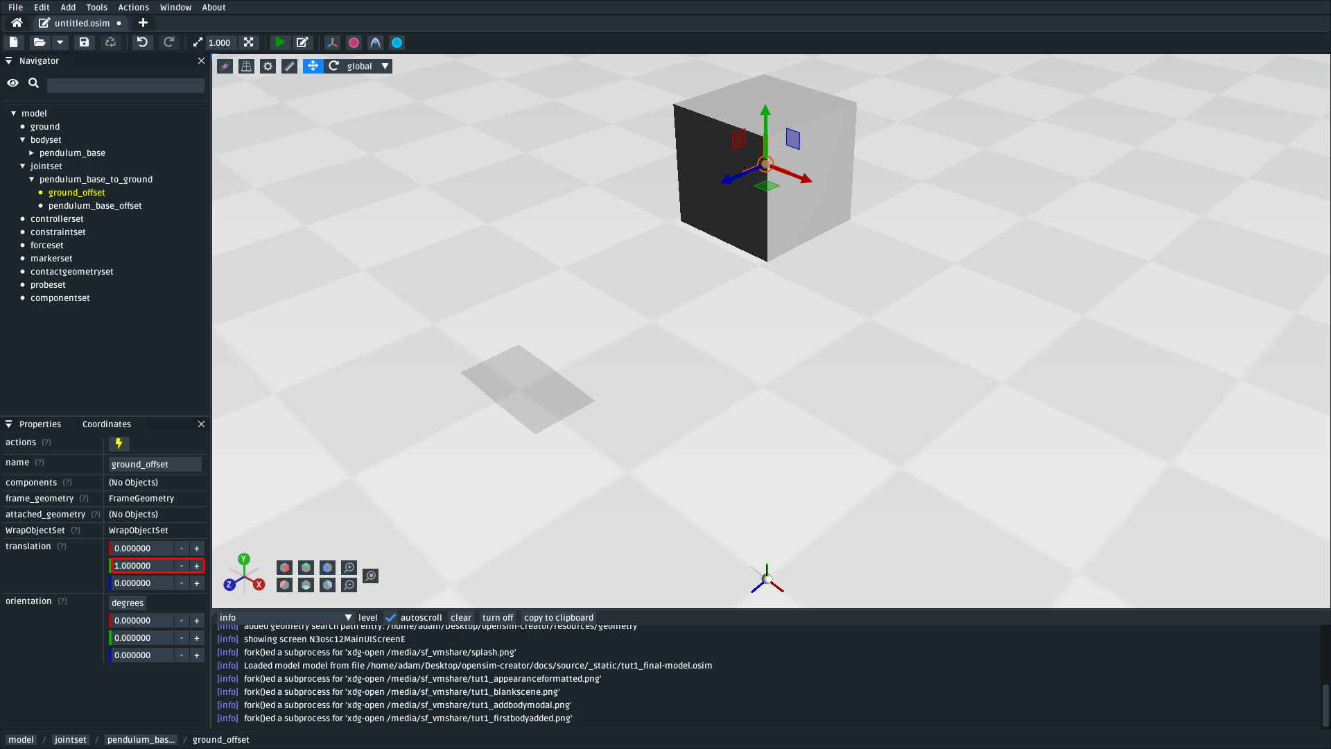
Fig. 1.6 Edit ground_offset’s translation Y value to move the pendulum_base away from ground in the scene. Changing it also changed where pendulum_base is in the scene because of the topographical relationship between pendulum_base and ground_offset (download model).#
Note
Although this is only a small part of the model-building process, this first step covers a lot of core OpenSim topics such as adding bodies, selecting joints, attaching frames to each other, and understanding the relative coordinate system.
Try to get familiar with these basics. You will encounter them frequently when using OpenSim. Experiment by changing the translation of the other offset frame (base_offset), use negative translations, attach different geometry, or change the geometry’s appearance (for a Brick, half widths can be changed to make it smaller/bigger).
1.6. Add the Pendulum Head#
In the previous step, we created pendulum_base, which is a body that is “welded” into the scene at some vertical (Y) offset. The next step is to create a pendulum_head that is attached to pendulum_base with a PinJoint. A PinJoint has one rotational degree of freedom along Z, which will enable the pendulum_head to swing relative to pendulum_base.
In the UI, add another body. Create it with the following details:
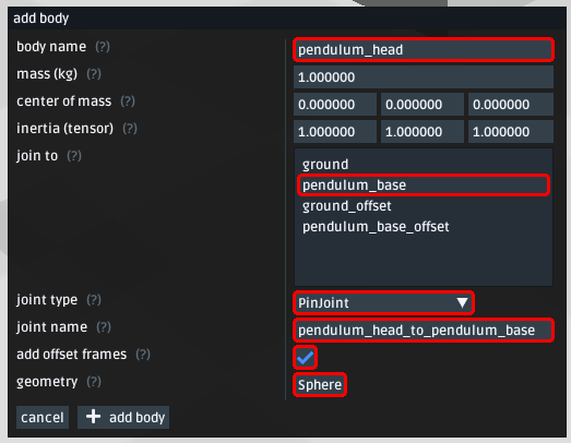
Fig. 1.7 pendulum_head’s’ body properties. Note: Make sure join to is set to pendulum_base and to also attach a Sphere generated geometry so the body so that you can see it in the visualizer.#
Warning
This should add pendulum_head into the scene. However you may not be able to see it yet. This is because pendulum_head is initially at the exact same location as pendulum_base (it’s attached to it) and its representation (a Sphere) is smaller than pendulum_base’s Brick, so it’s initially inside pendulum_base.
Next, we need to move pendulum_head such that it is below pendulum_base in the scene. It’s best to keep the model’s topology in mind when doing this. After adding pendulum_head, the new model graph looks something like this:

Fig. 1.8 Topology of the model after adding the pendulum_head body (and associated joint and offset frames).#
The model’s topology may look complicated but keep our main goal in mind: we want pendulum_head to be offset from the PinJoint that it will be swinging on. Therefore, we need to change the translation property of the pendulum_head_offset that the PinJoint (pendulum_head_to_pendulum_base) is attached to.
To change the offset between the pendulum head and the PinJoint it swings on:
Find
jointsetin the Navigator panel and expand itFind
pendulum_head_to_pendulum_basein thejointsetand expand itFind
pendulum_head_offsetunder that and click itUse the properties panel to change
pendulum_head_offset’stranslationproperty to(0.0, 0.5, 0.0)
After setting pendulum_head_offset’s translation to (0.0, 0.5, 0.0), you should be able to see the pendulum head floating below the pendulum_base:
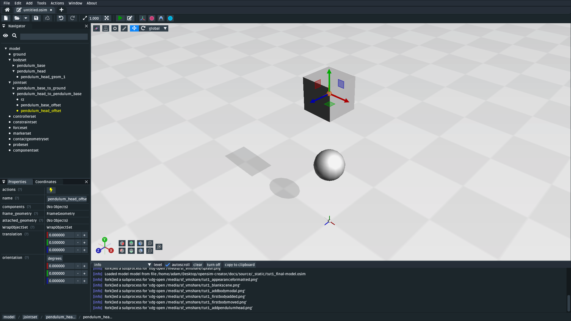
Fig. 1.9 How the scene should look after adding pendulum_head (a Body) and setting pendulum_head_offset’s translation property to (0.0, 0.5, 0.0). The sphere is the decoration for pendulum_head and the cube is the decoration for pendulum_base (download model).#
Note
We just set the translation property of pendulum_head_offset to +0.5 in Y, but it moved down, not up, in the scene. Why?
It’s because of how the relative coordinate system interplays with the topology of the model.
Looking at the topology graph (above), you’ll see that the PinJoint is attached to both the pendulum_head_offset and pendulum_base_offset frames. The PinJoint enforces that the two frames its attached to are constrained to the same location (the only degree of freedom a PinJoint has is its single rotational axis). By setting pendulum_head_offset’s translation to (0.0, 0.5, 0.0), we are stipulating that pendulum_head_offset must be 0.5Y above pendulum_head (in pendulum_head’s coordinate system). The only way to do this, while ensuring that pendulum_head_offset is still at the same location as the PinJoint, is to put the pendulum_head 0.5Y below pendulum_head_offset in the scene.
A rule of thumb for understanding how OpenSim resolves locations in the scene is to mentally traverse the topology graph. Start at the ground, which must be at (0.0, 0.0, 0.0), and work towards what you are working on (in this case, pendulum_head). Each element you encounter (e.g. a body, a PinJoint, or an offset frame) may additively enforce some kind of constraint or change in orientation. A “hacky” trick is just to play around with the offsets to get an idea of their overall effect on the model’s layout.
1.7. Pre-Swing the Pendulum Head#
Next, we are going to rotate the pendulum head along its swing direction slightly. At the moment, pendulum_head is directly below pendulum_base. The only force acting on the scene is gravity, so the pendulum head won’t move when we simulate it. You can see this problem for yourself by running a simulation. The scene should be motionless.
We can “pre-swing” pendulum_head a little by starting it off at an angle. The PinJoint we used to attach the pendulum head to the pendulum base (pendulum_head_to_pendulum_base) has a single degree of freedom, rz, which is exposed as a coordinate that can be edited. When the PinJoint was added, rz was given a default value of 0.0 (no rotation). You can edit the default_value property of rz to rotate pendulum_head along the PinJoint’s degree of freedom slightly.
To change the rx coordinate of pendulum_head_to_pendulum_base:
Find
jointsetin the Navigator panel and expand itFind
pendulum_head_to_pendulum_basein thejointsetand expand itFind
rzand click itUse the properties panel to change
rz’sdefault_valueproperty to1.0(radians)
After changing rz, the pendulum head should be rotated slightly:
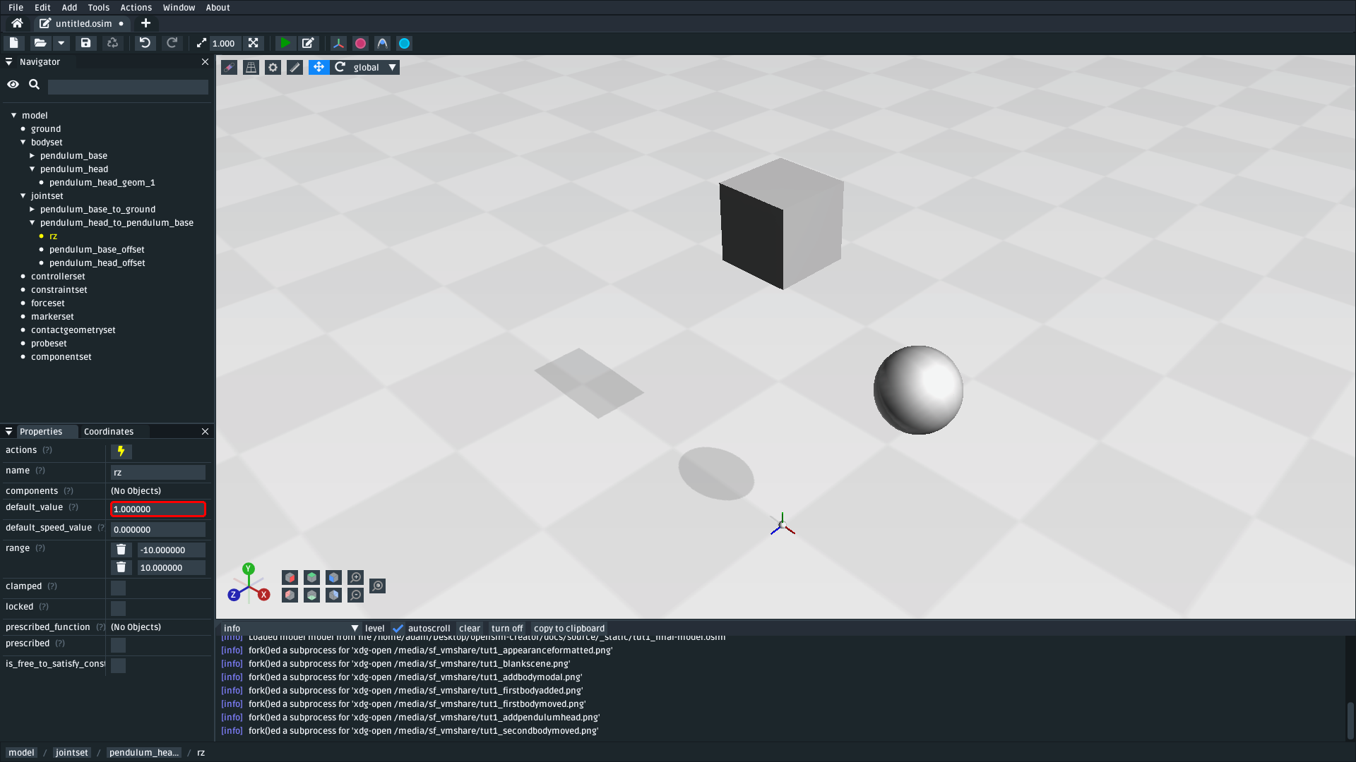
Fig. 1.10 The pendulum after modifying the PinJoint’s rz default_value. By modifying the coordinate value, we are changing the angle between pendulum_base_offset and pendulum_head_offset (the parent + child of the PinJoint). Because pendulum_head is attached to pendulum_head_offset, this has the overall effect of moving the pendulum_head (download model).#
1.8. Simulate the Model#
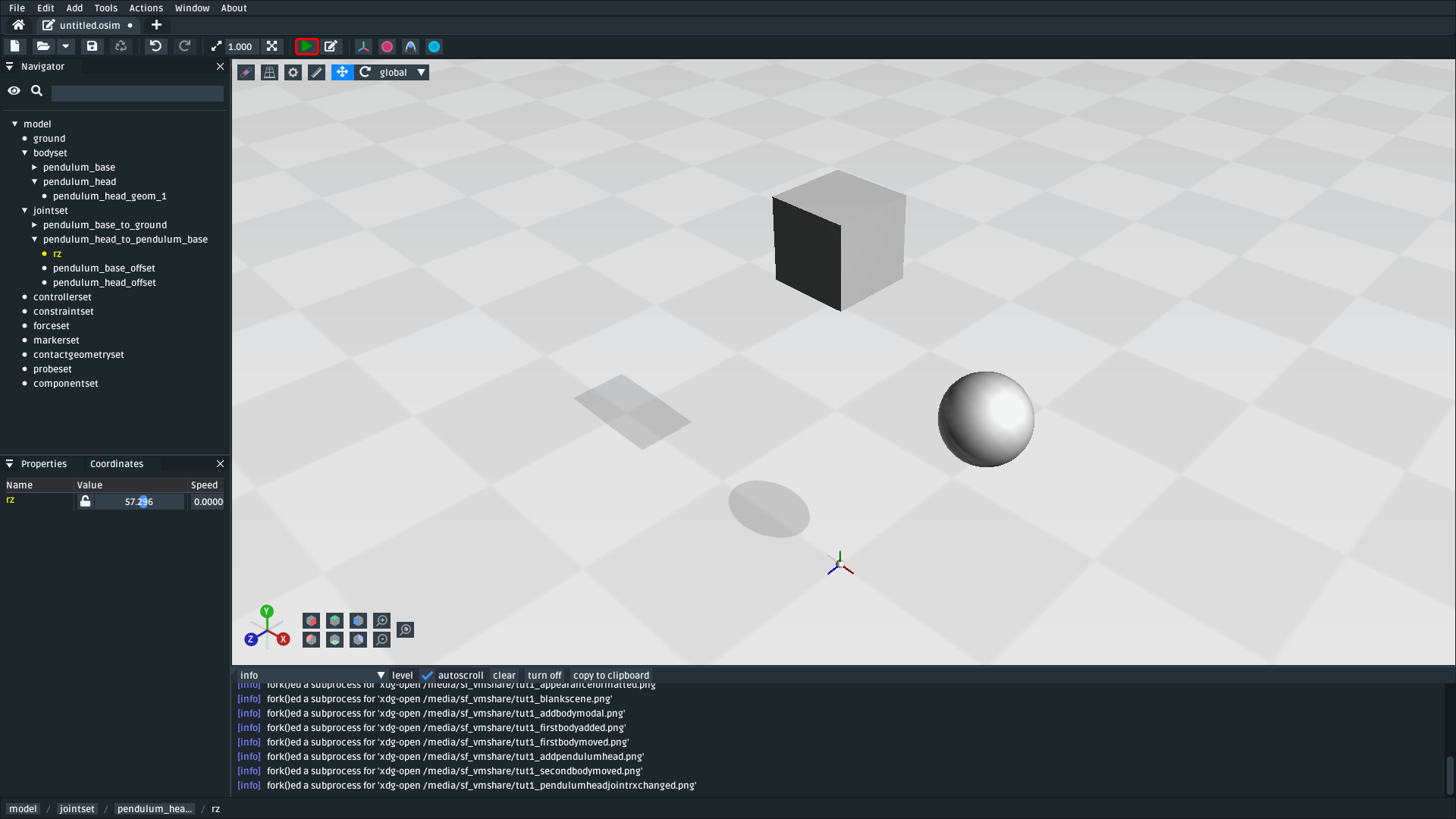
Fig. 1.11 Pressing the green Simulate button (or Ctrl+R) will start a forward-dynamic simulation of your model.#
OpenSim Creator contains buttons to start a forward-dynamic (FD) simulation. An FD simulation will simulate your model’s traversal through time by integrating things like forces, velocities, and positions over time.
If you simulate your pendulum model at this point (e.g. by pressing the green button, or Ctrl+R), you should see that pendulum_head swings like a pendulum 😊, which means you’ve succeeded!
Note
Hooray 🎉, we have created a functioning pendulum by adding two bodies and two joints into a model.
Think about that for a second: at no point in this tutorial did we add anything pendulum-specific into the model (e.g. the pendulum equation). Instead, we created a physical system that has the same topology and constraints as a pendulum and simulated that system. The simulation then produced the same behavior as an ideal pendulum.
This approach can be extremely useful. It lets us design physical systems on a computer from basic building blocks, followed by simulating those systems to yield physically-representative data. That data can then be compared to scientific predictions, or experimental measurements, to provide a deeper insight.
Although a pendulum may not be all that impressive, the principles shown here scale more easily to complex systems. Maybe the pendulum equation is simple, but what about a double pendulum, or (dare we suggest) a triple pendulum? What if we attach the pendulums to each other with springs, or muscles? What about a human leg containing many bodies, muscles, and joints that are attached to each other?
1.9. (optional) Make the Pendulum Look Nicer#
Although we have logically modelled a pendulum that meets our requirements (i.e. a mass joined at some distance to a pivot point), our model certainly doesn’t look like a pendulum. Lets fix that.
First, we can make the base into a thinner ceiling-like brick by changing the Brick’s half_lengths property:
Click the
pendulum_base’s cube in the visualizer, or browse topendulum_base_geom_1in the navigator panelUse the properties panel to change
pendulum_base_geom_1’shalf_lengthsproperty to something like(0.2, 0.01, 0.2). This property only represents the appearance of the model, not the behavior.
Next, we can make the pendulum head a little smaller by changing the Sphere’s radius property:
Click the
pendulum_head’s sphere in the visualizer, or browse topendulum_head_geom_1in the navigator panelUse the properties panel to change
pendulum_head_geom_1’sradiusproperty to something like0.05
Finally–and this is the hardest part–we need to add a Cylinder between the pendulum_head and the PinJoint. The cylinder will act as the pendulum’s neck. The easiest way to do this is to add an offset frame between the base and the head (i.e. 0.25Y above pendulum_head) and attach a Cylinder decoration to that frame. To do this:
Select
pendulum_headin the navigator panel (underbodyset)Open
pendulum_head’s context menu by either:Right-clicking it in the navigator panel
Clicking the lightning (“actions”) icon
Open the
Addmenu and clickOffsetFrameThis should create and select
pendulum_head_offsetframeUse the properties panel to set
pendulum_head_offsetframe’stranslationproperty to(0.0, 0.25, 0.0). This movespendulum_head_offsetframebetween the base and the head.Open
pendulum_head_offsetframe’s context menu by either:Right-clicking it in the navigator panel
Clicking the lightning (“actions”) icon
Open the
Addmenu and clickGeometryto add aCylindertopendulum_head_offsetframe(pendulum_head_offsetframe_geom_1).Click the cylinder in the visualizer, or find
pendulum_head_offsetframe_geom_1in the navigator panelUse the properties panel to set
pendulum_head_offsetframe_geom_1’sradiusproperty to0.01and itshalf_heightproperty to0.25
Once you’ve done that, you should end up with a more convincing-looking pendulum:
Fig. 1.12 Final pendulum model after updating the appearance (download model).#
1.10. (Optional) Extra Exercises#
Make a double pendulum. Using similar steps to the ones above, create a second pendulum head that attaches to
pendulum_headrather thanpendulum_base. This will create a double pendulum. An alternative solution to this exercise is covered in Use the Mesh Importer.Open the pendulum in the official OpenSim GUI. Save your pendulum to an
.osimfile and open it in the official OpenSim GUI. This will give you the chance to view your model in other software, which might give you extra modelling options (e.g. different plotting tools, more functionality).
1.11. Next Steps#
Although the model created here is simple, this tutorial had to introduce quite a few OpenSim concepts that you will repeatably encounter. Concepts like bodies, joints, constraints, and the relative coordinate system.
The next tutorial will reinforce these concepts by creating a more complex (but not quite biomechanical, yet 😉) model using these concepts, while introducing new things like collision detection and data extraction.