
4. Make an Arm#
In this tutorial, we will be using OpenSim Creator to create a basic human hand from some mesh files:
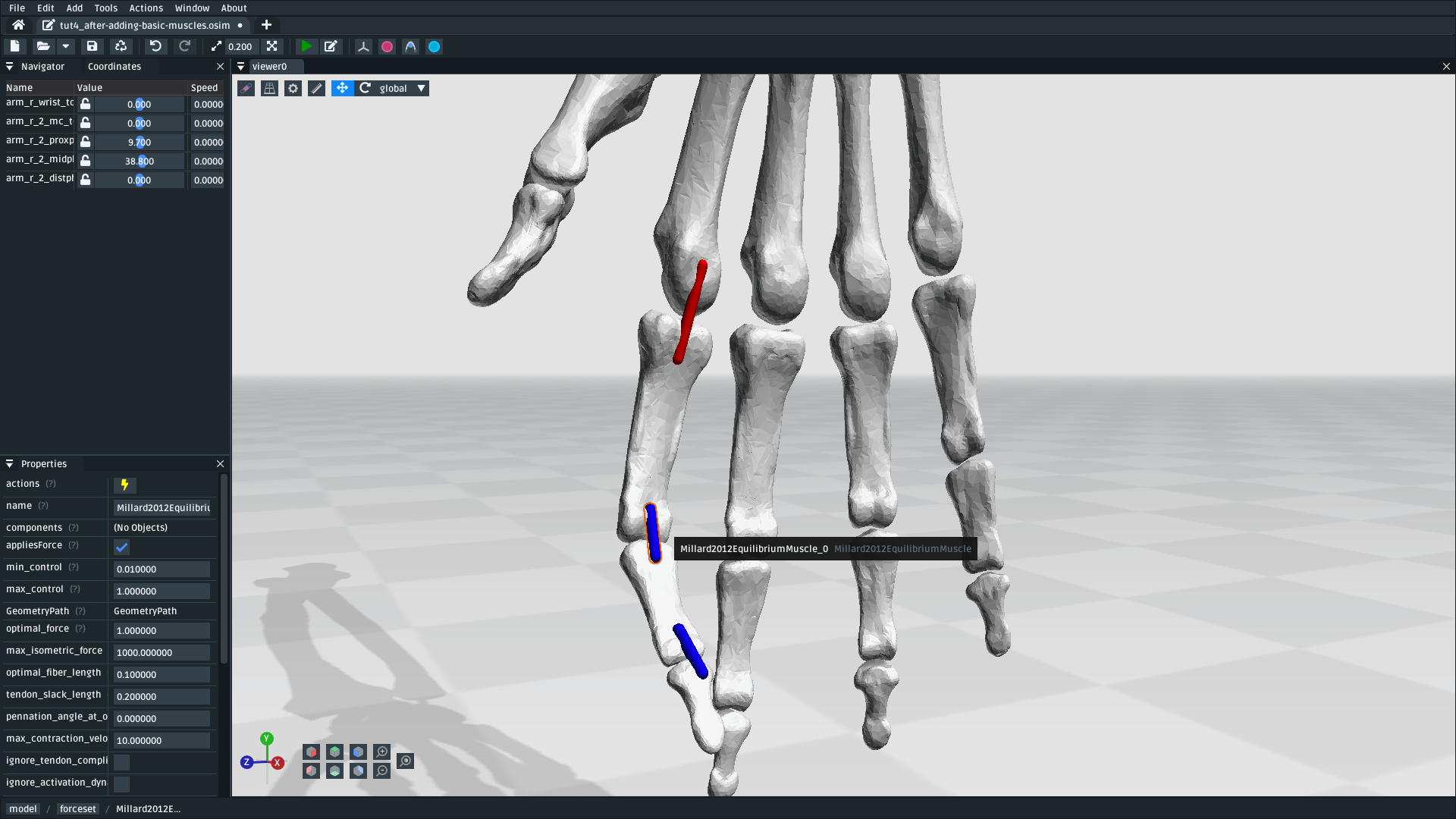
Fig. 4.1 The model created from these meshes. Final version of the model available here download model#
This tutorial will use the mesh importer to import mesh files that represent an arm, followed by using the mesh importer to assign the meshes to custom-placed bodies and joints. Once those are placed, the tutorial then introduces using stations to mark “points of interest” that can be used in the osim editor to define muscle paths.
4.1. Prerequisites#
This is a harder tutorial that builds on top of several techniques that were demonstrated in previous tutorials:
Make a Pendulum: Adding components into an osim, editing component values
Make a Bouncing Block: Adding forces into a model, making refinements/simplifications based on preliminary simulation results
Use the Mesh Importer: Importing meshes and placing bodies/joints with the mesh importer
Those techniques are used ad nauseam in this tutorial. Therefore, it is strongly recommended that you consult those tutorials if you aren’t sure what’s going on here.
4.2. Topics Covered by this Tutorial#
Importing meshes with the mesh importer.
Using the mesh importer to attach meshes to bodies and join bodies with joints
Using the mesh importer to mark points of interest in the model by adding stations
Using the
osimeditor to add muscle paths to the model
4.3. Import Meshes#
The first step is to get these meshes into OpenSim Creator. The easiest way to do this is with the mesh importer screen, which was described in Use the Mesh Importer. You need to:
Open OpenSim Creator’s mesh importer screen
Import these
meshesby either:Using the Meshes button in the right-click menu
Dragging & dropping the mesh files into the mesh importer screen.
Move all the meshes together such that they are above ground
This will give you a scene with the meshes in roughly the right place:
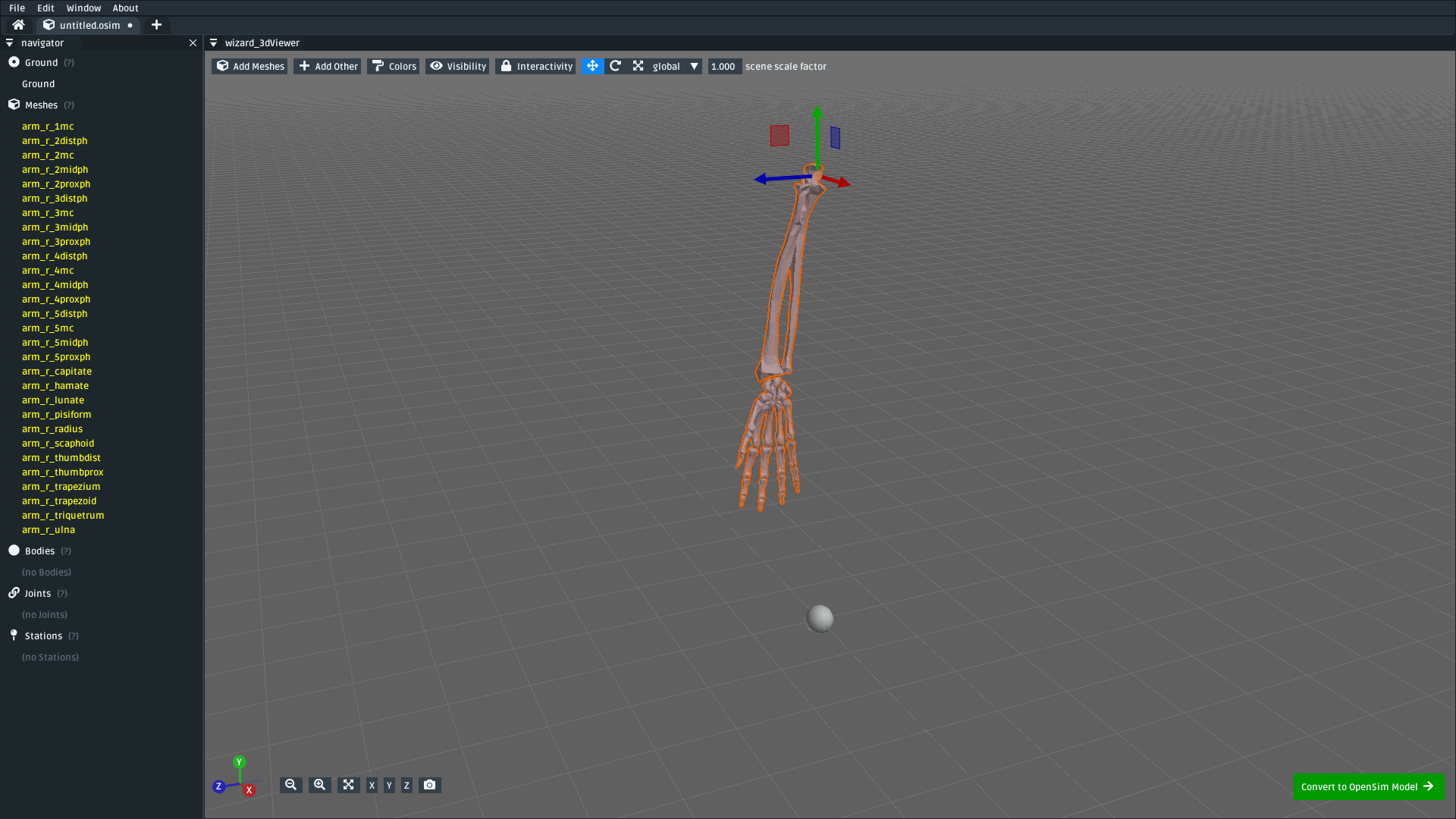
Fig. 4.2 The mesh importer screen after initially importing the meshes and moving them above ground.#
4.4. Add Bodies to the Meshes#
The next step is to place bodies in the model. As described previous tutorials, bodies are (effectively) points in space with a mass. In this step, we are going to add bodies where we think the main mass centers in the model should be (based on the meshes) and attach the meshes to the bodies. Attaching the meshes ensures that the mesh moves along with the body, rather than being immobilized in ground.
Note
Change the mesh importer’s scene scale factor to 0.1 for this, which is smaller than the default (1.0). The scale factor has no effect on the model, but makes it easier to place bodies/joints in smaller meshes.
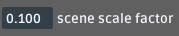
Fig. 4.3 Adjust the scene scale factor to 0.1.#
To keep things short, we will initially only assign bodies to the model’s index finger. To do that:
For each of the four bone meshes in the index finger (
arm_r_2distph,arm_r_2midph,arm_r_2proxph, andarm_r_2mc):Right-click the mesh then navigate to
Add > Bodyand clickAt Bounds Centerto add a mesh at the center of the mesh’s bounds. Alternatively, hover the mesh and press theB(add body) hotkey, which places a body where the mouse is currently hovered.Right-click the added body, rename it to the mesh name followed by
_b(to indicate body). E.g.arm_r_2distph_b
As a simplification, only add one body to the mesh in the middle of the wrist. For example, add one to
arm_r_capitateand call itarm_r_wrist_b(because it will act as a body for all wrist bones).As a simplification, only add one body to the arm and move it between the arm mesh bones. For example, add one to
arm_r_radiusand call itarm_r_b(because it will act as the body for both theradiusandulna).
Note
Sage tip 🧙: when you’re having problems seeing/clicking things, try changing your visualization options.
The mesh importer has options for changing the colors, visibility, and interactivity of various scene elements (e.g. meshes). These options can be very useful when working on complicated models, like this one, because your scene may end up containing a lot of overlapping geometry (e.g. bodies embedded inside meshes).
This will yield a model with all the meshes imported and six bodies added into the scene. In my case, the six bodies were called:
arm_r_2distph_barm_r_2midph_barm_r_2proxph_barm_r_2mc_barm_r_wrist_barm_r_b
The model should look something like this:
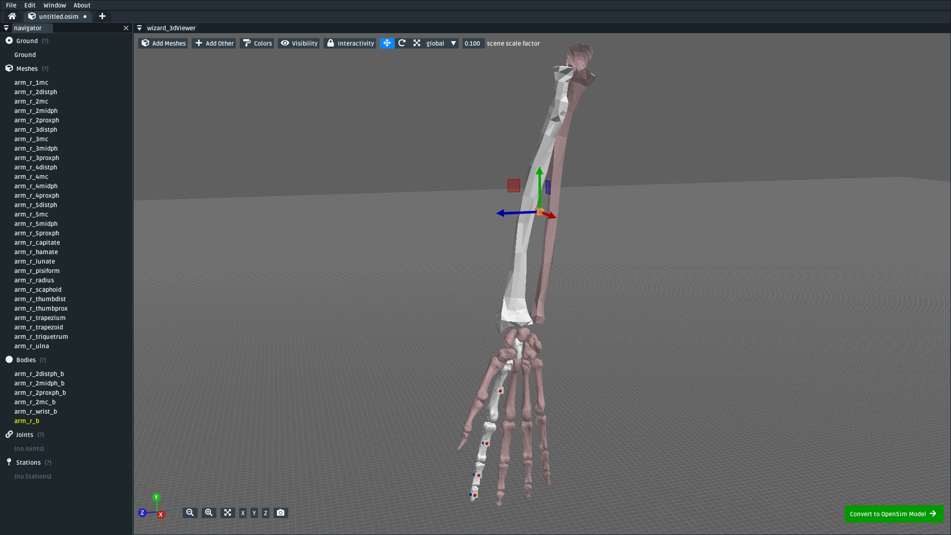
Fig. 4.4 The scene after assigning the first six bodies for the index finger up to the arm. When hovering something, grey lines in the UI indicate the connectivity between the bodies. download model#
4.5. Assign Unassigned Meshes to Appropriate Bodies#
We also need to assign the unassigned meshes to each body.
When we imported the meshes, they were imported as unassigned (i.e. attached to ground). Unassigned meshes are slightly red-tinted compared to assigned meshes.
For this model, we will assign the finger, wrist, and arm meshes to the appropriate bodies. The other finger meshes are attached to the wrist body so that they move whenever the wrist moves - even though they haven’t had all of their bodies/joints assigned yet.
To (re)assign a mesh, right-click the mesh, click reassign connection > parent, then click the body the mesh should be attached to. Alternatively, you can hover over the mesh and press A (assign). You need to assign the following meshes:
Attach all wrist bone meshes to the wrist body (
arm_r_wrist_b)Attach the unassigned ulna arm bone mesh (
arm_r_ulna) to the arm body (arm_r_b)
This should result in most of the model being assigned. I have skipped assigning the other fingers, but you can do it if you want (assign each of the unassigned finger bone meshes to arm_r_wrist_b):
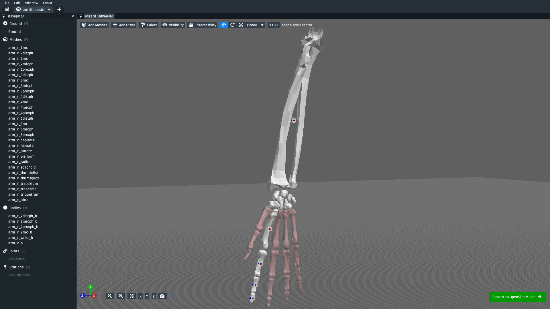
Fig. 4.5 The scene after assigning the bone meshes to the corresponding bodies. Here, the other finger meshes are left unassigned. You can (optionally) assign them to the wrist body (arm_r_wrist_b) if you would like them to track along with the wrist. download model#
4.6. Add Joints Between the Bodies#
Now that we have roughly positioned our bodies in the scene, the next step is to place joints between those bodies.
Joints express how the bodies can move relative to each other. In this (simplified) model, we will assume all parts of the finger and wrist can be attached to each other with pin joints. This isn’t technically true, but it is close enough quickly build a model that can be simulated. The joint type can be changed to a more suitable joint (e.g. a custom joint) later.
To add pin joints between each body:
Right-click the body at the end of the finger (e.g.
arm_r_2distph_b) and clickJoin To. Alternatively, hover over the body/mesh and pressJ(join to).Select the body it should attach to (e.g.
arm_r_2midph_b), this will create aWeldJointjoint center between the two bodies.Right-click the joint center and change its joint type to a
PinJoint. Alternatively, you can right-click the joint in the navigator panel.Right-click the joint center and change its name to something that describes the connection (e.g.
arm_r_2distph_to_2midph).Move the joint center to where it should be (i.e. between the bones). The
Translate > between two mesh pointsmenu can be handy here.Rotate the joint center such that X is oriented toward the parent (here:
arm_r_2midph_b) and Z is where the “pin” should be. TheReorient > X > towardsmenu is handy for this, follow it up by rotating (R) along thelocalX axis to positionZ.
You should also add a weld joint between the arm body (arm_r_b) and ground. This will anchor the model relative to ground, preventing it from falling or flopping around.
Note
Knowing the available translation/orientation options makes this part easier.
Whenever you select something in the editor, you can translate/orient them by:
Dragging them in the 3D scene using the drag or rotation handles. You can switch between the handle type by either pressing the grab (
G) hotkey or the rotate (R) hotkey, or by changing thetranslatedropdown at the top of the UI torotateRight-clicking and typing values into the
TranslationandRotationboxes. These values are absolute.Right-clicking and using the
translateandreorientsub-menus, which include handy macros likereorient > X > towards parent
The editor also supports switching between local and global coordinate spaces for the drag/rotation handles. This lets you rotate along an axis, which is particularly handy if you use something like reorient > X > towards parent followed by rotating along X to position the other two axes.
Following these steps, you should end up adding six joints (five pin joints, one weld joint) into the scene. In my case, the names of the joints were:
arm_r_2distph_to_2midpharm_r_2midph_to_2proxpharm_r_2proxph_to_2mcarm_r_2mc_to_wristarm_r_wrist_to_armarm_r_to_ground(WeldJoint)
And the scene looked as follows:
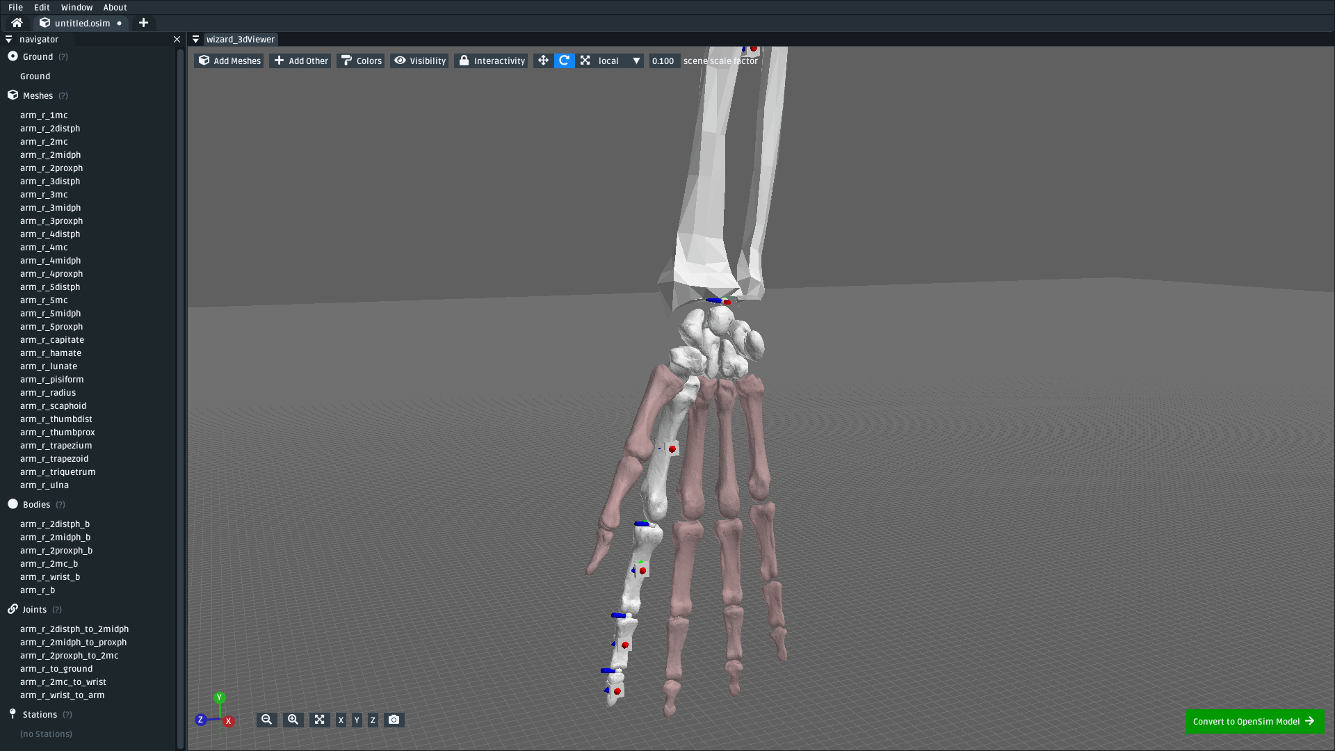
Fig. 4.6 The scene after adding five pin joints between the six bodies and one weld joint between the arm and ground. The pin joints were placed between the meshes, roughly where the joint is expected to be. The Z axis of each pin joint’s center is the axis the pin rolls along. The weld joint was moved to the location of arm_r_b. download model#
(optional) Now that you’ve assigned some bodies, meshes, and joints, this is now a good time to spot-check your model. To do so, click the Convert to OpenSim model button, which should put your scene in the osim editor. You can then change some of the joint coordinates to see if the finger moves as-expected:
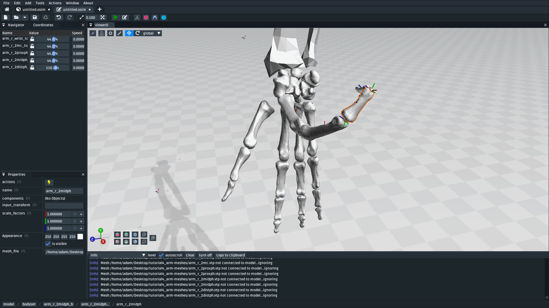
Fig. 4.7 (optional) Now that bodies, meshes, and joints have been added via the importer, you can test your progress by importing the scene into the osim editor and changing a few joint coordinates. The unassigned meshes might look unusual (they will stay where they are, in ground, when the wrist moves), but the rest of the finger should move roughly as expected.#
4.7. Mark Points of Interest on the Meshes#
Now that we’ve added bodies, meshes, and joints, the next step is to think about where we will ultimately be placing muscles.
Although the mesh importer doesn’t directly support defining muscles, it does support placing stations in the scene. A station is some location in the scene that is attached to something else (typically, a body). When the scene is converted into an osim, the station will be attached to the appropriate exported object and expressed in OpenSim’s relative coordinate system.
The utility of adding stations is that they’re relatively easy to (re)attach, and move around, while working in the mesh importer. Once exported, the exported (OpenSim) stations can later be used to easily define a muscle path. Usually, defining a muscle path is challenging because it requires figuring out the relative coordinates of each muscle-path-point within each frame. However, stations already cover the point-within-a-frame part of that definition, leaving you to focus on connecting them to create paths.
To add stations into the model:
Right-click a mesh, navigate to
Add > Stationand clickAt Click Position. This will add a station wherever you right-clicked on the mesh. The station will be attached to whatever the mesh was attached to (e.g. right-clickingarm_r_2distphand adding the station will attach it toarm_r_2distph_b). Alternatively, you can hover over where you want the station and pressT(for s t ation - yes, the keybinds could use some work 😛)If the station isn’t attached to the correct body, fix it by right-clicking the station and
Reassign Connection.The station can be freely moved around in the scene. It only has a position (no rotation).
Use the above points to assign muscle origin ${name}_orig and insertion ${name}_ins points into the scene:
Add an insertion point at the end of the finger (
arm_r_2distph), call itarm_r_2distph_insAdd the corresponding origin point to the next bone up (
arm_r_2midph), call itarm_r_2midph_origRepeat the process for each bone in the finger (
arm_r_2midph,arm_r_2proxph,arm_r_2mc), finishing with an origin point on the wrist (arm_r_trapezoid)
This should result in eight stations with the following names (see figure below):
arm_r_2distph_insertionarm_r_2midph_originarm_r_2midph_insertionarm_r_2proxph_originarm_r_2proxph_insertionarm_r_2mc_originarm_r_2mc_insertionarm_r_wrist_origin
The stations should be placed in similar position to the figure below. These stations will be what we use when defining muscle paths later.
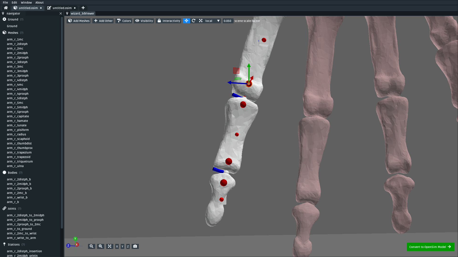
Fig. 4.8 The scene after defining eight stations along the index finger. These stations are “points of interest” that can be used later to define muscles. The utility of adding them now is that the mesh importer makes it easy to place, reattach, and move them around in the scene. download model#
4.8. Convert to an OpenSim Model#
Now that we have added meshes, bodies, joints, and points of interest into the mesh importer, we are now (finally 🎉) ready to import the scene into an osim, check for any basic issues, and perform any osim-specific steps.
To convert and check the model:
Press the
Convert to OpenSim modelbutton:This imports the mesh importer scene into the
osimeditorYour progress in the mesh importer is not lost, if you reopen the mesh importer tab you should still be able to see your scene as it was before converting it
Experiment with changing model coordinates:
This should move parts of the finger
Run a basic forward-dynamic simulation of the model
Press
Ctrl+Rto start simulating the model, or click theSimulatebuttonThe arm should flop around in the scene. Unassigned (red) meshes will be anchored to ground.
This is a basic check to ensure the model at least simulates (even if it’s not a particularly interesting simulation)
You should be able to see the meshes, see that the joints are rotating (somewhat) correctly, and see the stations. If there are any problems, then return to the mesh importer and fix things.
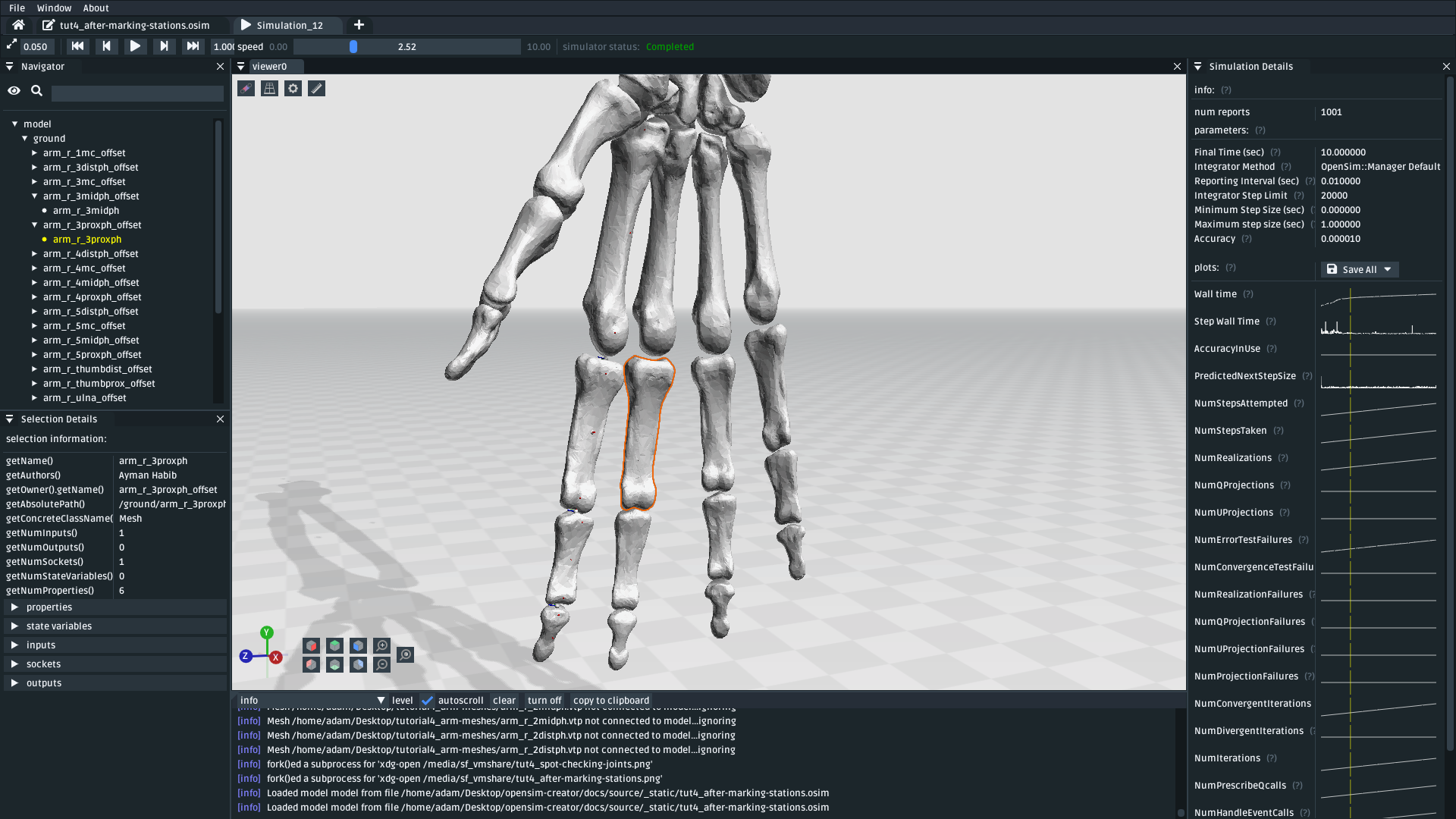
Fig. 4.9 The osim model created from the mesh importer. Editing joint coordinates and simulating the model is a quick way to check if joint centers are correctly oriented. Here, you can see that the finger-to-wrist joint is off. This was fixed by returning to the mesh importer and reorienting that joint center. (download model)#
4.9. Add Muscle Paths#
Now that we have an actual OpenSim model (osim), we can add any OpenSim components we want into it. In this step, we will focus on adding muscles.
To add muscles between the stations we added in previous steps:
Make sure you have an
osimeditor window open (e.g. by exporing the model from the mesh importer)Open the
Addmenu from the main menu, or by right-clicking an empty part of the 3D sceneOpen the
Forcesubmenu and clickMillard2012EquilibriumMuscleIn popup, choose path points between the stations we previously defined, e.g.:
Add
arm_r_2midph_originas the first path point andarm_r_2distph_insertionas the second path point to create a muscle between the twoClick
Addto add the muscle into the model
Repeat the above for all the
_origin_insertionpairs created in Step 4
For example, this is how I added the first muscle:
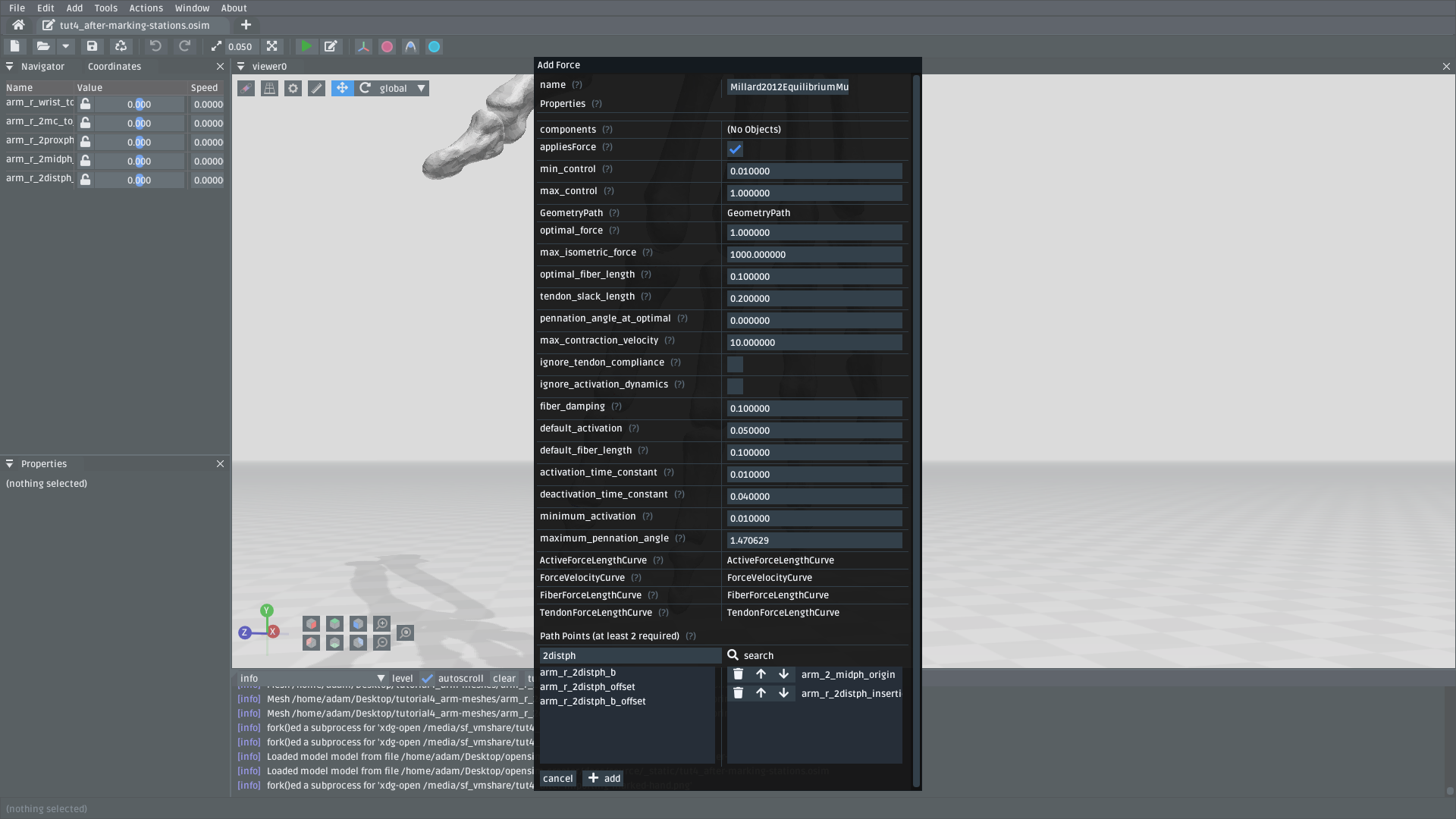
Fig. 4.10 Example of adding a muscle between the arm_r_2midph_origin and arm_r_2distph_insertion stations.#
Once all the (admittedly, basic) muscles have been added, you should now have the final model containing muscles 💪! Congratulations! It should look something like this:
Fig. 4.11 The final hand model after adding meshes, bodies, joints, stations, and muscles. This tutorial only covers modelling one finger, but the same techniques can be applied to create the whole hand.#
4.10. Summary#
In this tutorial, we covered a more complex modelling scenario. One where the model had to be created from a collection of mesh files. To keep the tutorial short, it only went through modelling one finger of the arm. However, the techniques covered here can be used to model the remaining fingers and to add more bodies into the wrist. The approach is largely the same.
This tutorial also covered using stations to mark out locations on the model. We then used the stations to add muscle paths between various parts of the model. The muscle paths added in this tutorial are extremely basic–they are just direct lines between the meshes–but more path points can be used to create a more realistic muscle path. To keep this tutorial short, we skipped doing that, but you can effectively just add more stations and chain them together when defining the path in the Add Force dialog. OpenSim also supports adding wrap geometry to muscle paths, enabling them to curve over things. OpenSim Creator doesn’t natively support this (yet), so you will need to figure out how to add those into the osim file manually.
Overall, the techniques demonstrated in this tutorial are useful if you want to get something into OpenSim fairly quickly. Once you have an OpenSim model (osim), you can then use the entire ecosystem to add many more features. The world (of OpenSim) will be your oyster 🦪!
4.11. (Optional) Extra Exercises#
Model the whole hand. This tutorial kept things short by only modelling one finger. However, the mesh files provided at the start contain the meshes for all bones in the lower right-arm. You should be able to use the techniques described here to assign bodies + joints to all relevant parts of the lower-arm, which will produce a much more convincing model.
Add other OpenSim components to your imported model. This tutorial only focuses on adding muscles, but OpenSim Creator also supports adding things like contact geometry, springs, and constraints. Try experimenting with OpenSim by adding some of these things - what’s the worst that could happen 😉
Edit the osim file directly in a text editor. OpenSim Creator only supports a subset of OpenSim because it takes time (and effort 😓) to add things into the UI. However, OpenSim Creator is able to load and view almost any OpenSim component - even if it can’t add the component itself. OpenSim Creator also supports hot reloading in the osim editor, which means edits to the underlying
osimfile should automatically reload in OpenSim Creator. This can be useful if you’re adding custom components via a text editor.