
5. Use the Mesh Warper#
Note
This documentation is ⭐new⭐.
If you find an error in this tutorial, or you feel that something is fundamentally missing, then post an issue at OpenSimCreator Issues
In this tutorial, we will be using the Mesh Warping UI to perform landmark-driven mesh warping using the Thin-Plate Spline algorithm (explanation, literature source). The UI provides tooling for loading two meshes and creating landmark pairs between them:
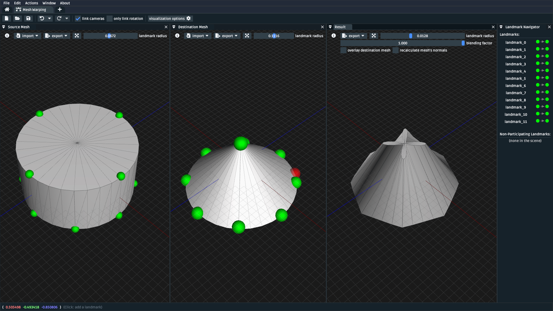
Fig. 5.1 A screenshot of the mesh warping UI, which shows the source (“reference”, left) destination (“target”, middle) and result (“warped”, right) meshes. Here, the warping quality is low. This is because of the low triangle and landmark count.#
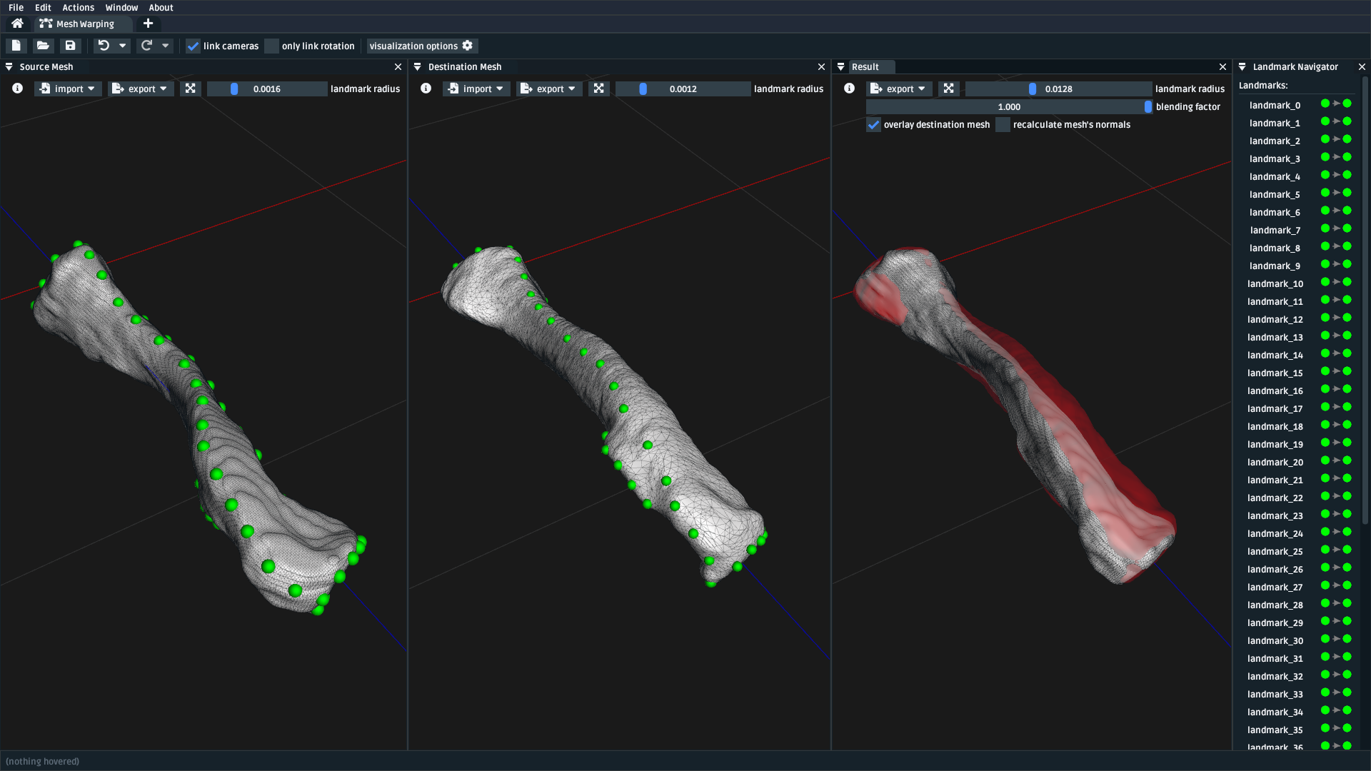
Fig. 5.2 Same as Fig. 5.1, but showing an example of warping a clavicle bone. This example has many paired (left-to-middle) landmarks in a variety of locations along the surface of the bone, which improves the warp quality (right).#
5.1. Prerequisites#
This is a standalone tutorial. The mesh warping UI is designed to be separate from OpenSim, so that it can specifically address the requirement of placing (+ pairing) landmarks on generic mesh files to perform non-uniform warping.
For your own work, you will need two mesh files that are logically pair-able with landmarks. For example, two femur meshes with boney landmarks that are present (albeit, possibly in a different location) in both meshes. The meshes do not need to be anatomical: you can also use this technique to morph between entirely abstract shapes.
5.2. Topics Covered by this Tutorial#
A theoretical overview of the underlying Thin-Plate Spline (TPS) technique
A high-level overview of how OpenSim Creator’s mesh warping UI works
A concrete walkthrough of using the UI on an anatomical mesh
5.3. The Thin-Plate Spline (TPS) Technique#
Note
This section isn’t going to explain the Thin-Plate Spline (TPS) technique in extensive detail. Instead, it will provide a simplified explanation that should be good enough to get an of what’s happening when you use the mesh warping UI.
If you want to know more about the TPS technique, we recommend consulting the Relevant References section, where we’ve listed a variety of relevant literature.
As a colloquial explanation, imagine placing a flat, thin plate with points along its surface onto a table. Now imagine that each of those surface points has a corresponding “target” point somewhere in 3D space. Now imagine you could bend the plate. If you could figure out an “optimal” way to bend it, you could minimize the distance between each surface point and its corresponding “target” point.
The TPS technique models that idea, but in \(n\)-dimensional space, by making several assumptions:
It describes “bending” the plate as a bounded linear combination of some basis function, \(U(v)\). The original paper used \(U(v) = |v|^2 \log{|v|^2}\), but other sources, including OpenSim Creator, use \(U(v) = |v|\).
It treats the problem of transforming “source/reference” points (landmarks), \(x_i\), to “destination/reference” points (landmarks), \(y_i\), as an interpolation problem.
And it solves the coefficients of that linear combination while minimizing the “bending energy”. Wikipedia example:
The coefficients that drop out of this process can then be used to warp any point in the same space. If you’d like to know more, we recommend the literature in the Relevant References section.
Here’s how these high-level concepts from the TPS technique apply to OpenSim Creator’s mesh warping UI, which internally uses the TPS algorithm:
Source Mesh and Source Landmark refer to data in the “reference”, or “source” space. Each source landmark requires a corresponding destination landmark with the same name.
Destination Mesh and Destination Landmark refer to data in the “target”, or “destination” space. Each destination landmark must have a corresponding source landmark with the same name.
Warp Transform is the product of the TPS technique after pairing the source landmarks with the destination landmarks and solving the relevant TPS coefficients. The warp transform can be applied to any point in the source space to warp it into the destination space. E.g. in the mesh warping UI, the transform is applied to the source mesh to produce the result mesh. It’s also applied to non-participating landmarks to produce warped data points.
Result Mesh is the result of applying the warp transform to the source mesh.
Non-Participating Landmark is a landmark in the source mesh’s space that should be warped by the warp transform but shouldn’t participate in solving the TPS coefficients.
5.4. Opening the Mesh Warping UI#
The mesh warping UI is an independent “workflow” UI that can be accessed from OpenSim Creator’s splash screen:
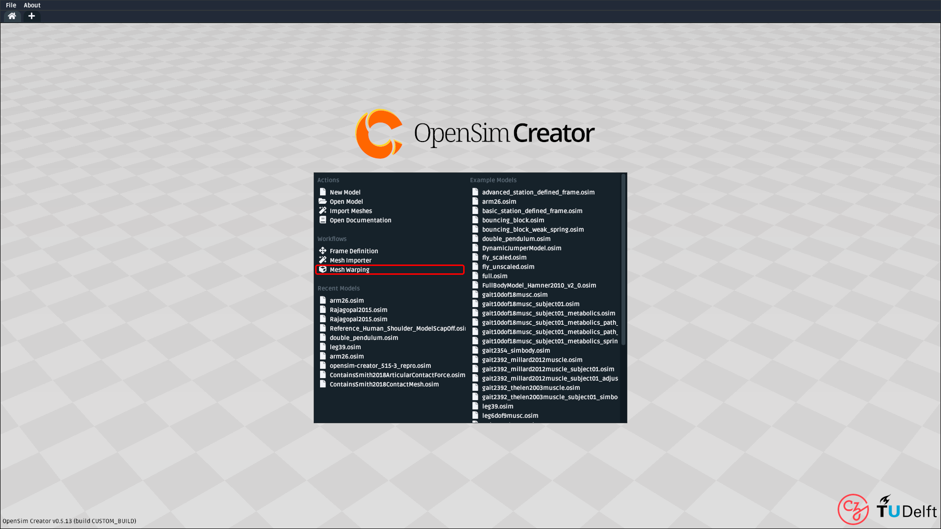
Fig. 5.3 A screenshot of OpenSim Creator’s main splash screen. The mesh warping UI can be opened from the main splash screen of OpenSim Creator (highlighted red).#
5.5. Mesh Warping UI Overview#
Fig. 5.4 A screenshot of the mesh warping UI with two clavicle meshes (+landmarks) opened in it. Left: the source mesh, with paired source landmarks shown in green. Middle: the destination mesh, with paired destination landmarks shown in green. Right: the result mesh, with the source mesh overlaid in red.#
The mesh warping UI uses separate windows to display relevant warp information. You can
toggle each window from the Window menu at the top of the UI. Here is how each
window relates to mesh warping and the TPS technique:
Source Mesh (window): shows the source mesh, source landmarks, and non-participating landmarks. Source landmarks that have no corresponding destination landmark (an unpaired source landmark) are displayed in red, paired landmarks in green, and non-participating landmarks in purple.
Destination Mesh (window): shows the destination mesh and destination landmarks. Destination landmarks that have no corresponding source landmark (an unpaired destination landmark) are displayed in red, paired landmarks in green.
Result (window): shows the result mesh and any warped non-participating landmarks. There’s also an option to overlay the destination mesh in this panel, which helps with evaluating how closely the result mesh (made by warping the source mesh) matches the destination mesh. There is also a
Blending Factorcontrol, which enables blending between “not warped” (i.e. source data) and “fully warped” on a linear scale.Landmark Navigator (window): shows each (source/destination/non-participating) landmark the UI is editing. This is handy when editing many landmarks.
Toolbar (top): the main feature of note here is the ability to (un)lock the camera, which can make viewing paired meshes easier.
How you use these panels is up to you. A typical workflow has these steps:
Import/generate meshes in the source mesh and destination mesh panels
Import landmarks into each panel, or
LeftClickon the mesh to place a landmark, orCtrl+LeftClickto place a non-participating landmark on the source mesh.View the result mesh and non-participating landmarks.
Export whatever you need elsewhere using the
Exportbuttons
Note
The main thing to take away from this high-level UI explanation is how each panel
relates to the underlying TPS technique and how data can be import ed and
export ed into each panel.
Apart from that, the easiest way to get familiar with the UI is to actually use it. We recommend “playing around” with some generated geometry, or mesh files, to “get a feel for the algorithm”, or continuing through this tutorial 📖
5.6. Walkthrough: Warping a Pelvis#
In this walkthrough, we’ll go through pairing landmarks between two pelvis MRI scans. For context, the pelvis scans we’re showing in this section were originally collected by Judith Cueto Fernandez and Eline van der Kruk, from the BODIES lab, who landmarked them in order to perform TPS-based model scaling in the model warper. Due to privacy reasons, we cannot provide the raw MRI scans. You should use your own mesh data for this section - the fact we’re using a pelvis isn’t significant for this tutorial.
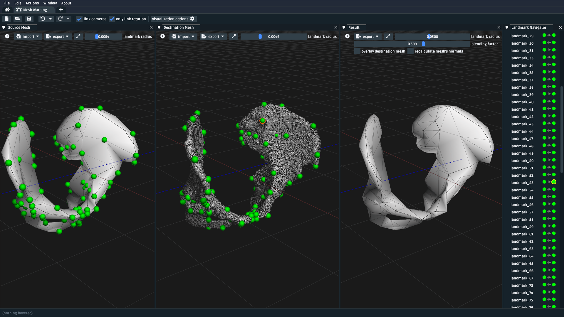
Fig. 5.5 A screenshot of the mesh warping UI with the two pelvis meshes opened, followed by opening the landmark CSVs for the source/destination. Left Mesh: the source mesh. Middle Mesh: the destination mesh. Right Mesh: the result mesh. The green spheres represent paired landmarks. Right Panel: the landmark navigator, which can be useful for figuring out which landmark is which.#
5.6.1. Load Raw Mesh Data#
Typically, the first step to take when warping a mesh is to load the raw mesh data for the source/destination into the mesh warping UI. To do that, we:
Ensured the
Source Mesh,Destination Mesh, andResult Meshpanels were opened via theWindowmenuOpened the source mesh via the
Importdropdown in the top-left of theSource Meshpanel, which shown the source mesh.Opened the destination mesh via the
Importdropdown in the top-left of theDestination Meshpanel, which shown the destination mesh.
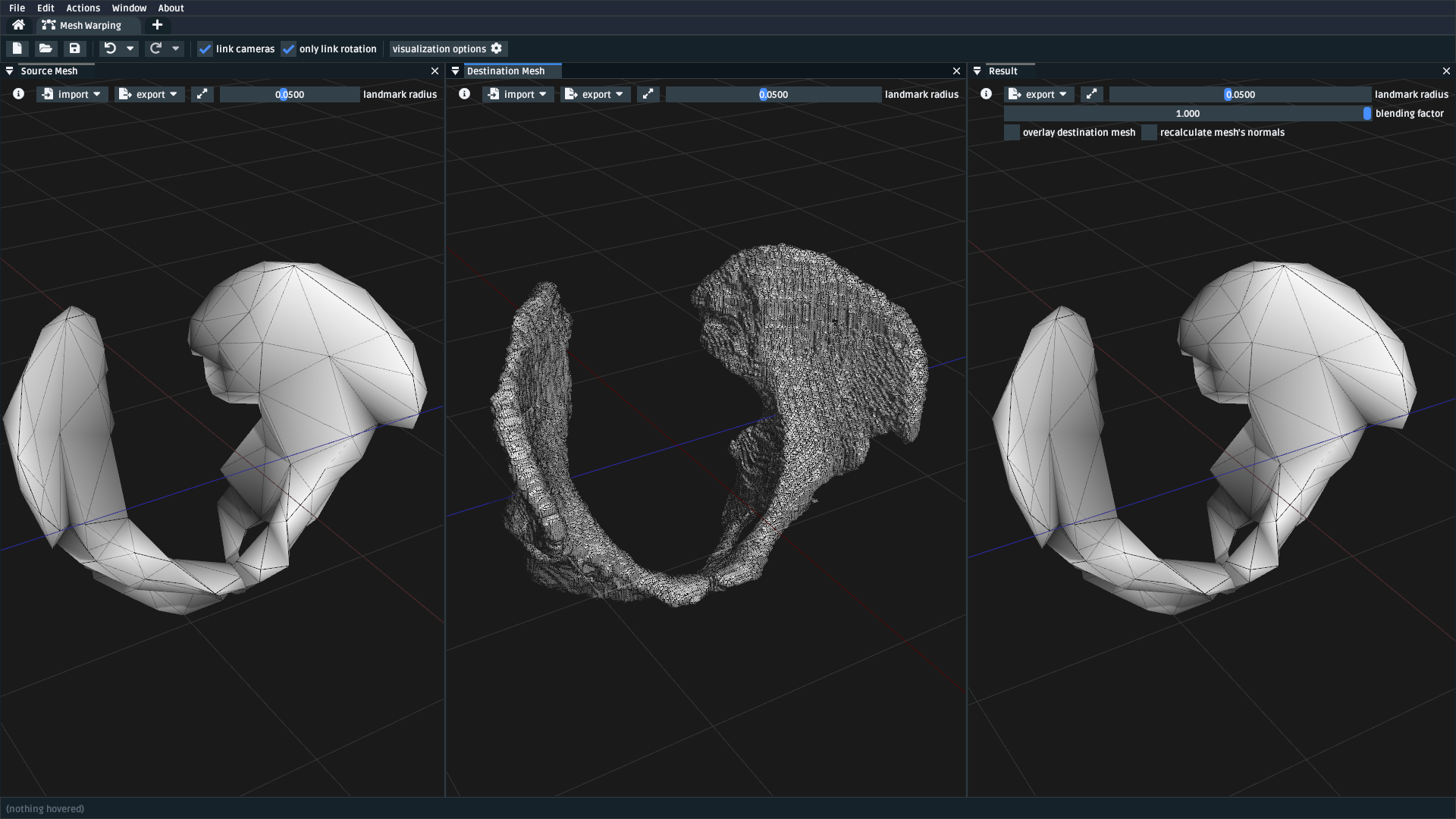
Fig. 5.6 A screenshot of the mesh warping UI after the source and destination meshes
are loaded via the import dropdown.#
5.6.2. Place Landmarks on the meshes#
After loading the meshes, the next step is usually to place landmarks. In this walkthrough’s case we:
Changed the
landmark radiusfrom 0.05 to 0.005, because the pelvis meshes are quite small (larger landmarks can drown out the mesh).Used the mouse to place a landmark on the source mesh, which initially appears red because it has no corresponding point.
Used the mouse to place a landmark on the destination mesh, which appears green, and changes the source landmark’s color to green, because it is fully paired with the first landmark.
Repeated this process for 3 or 4 more pairs.
After doing this, you’ll end up with something like the figure below. The key
features when landmarking are that you can always delete a landmark with the Delete
or Backspace key, Undo/Redo work as normal, and the right-click context
menu manipulates the pair (e.g. Delete ing via the context menu will try
to delete both participants in the pair).
You’ll also notice that, while we generally don’t interact much with the Result Mesh
panel when landmarking, it’s useful for getting an idea of how well the Thin-Plate
Spline (TPS) technique is able to morph the source mesh to “fit” the destination mesh.
Playing around with the blending factor slider helps to show how the morph could
be incrementally applied to the source data, and there’s also an
overlay destination mesh option, which helps with visually evaluating the
fitting quality.
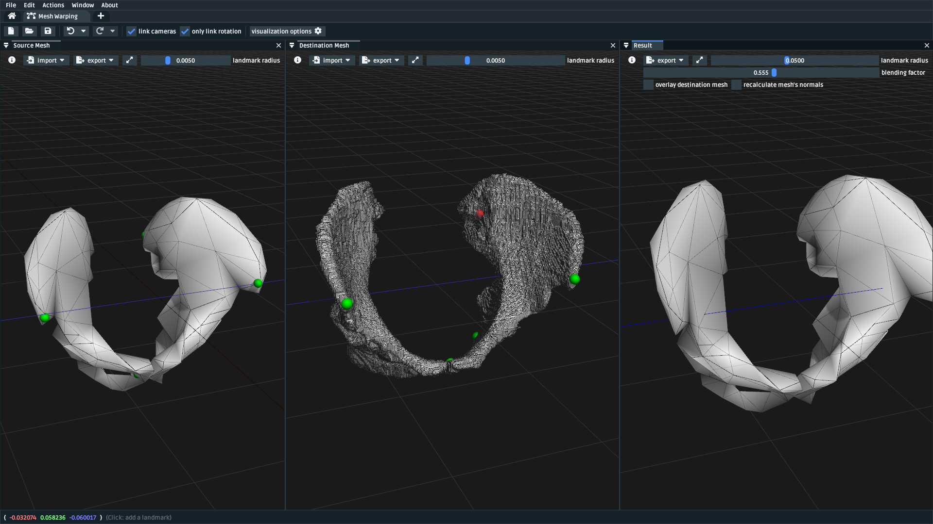
Fig. 5.7 A screenshot of the mesh warping UI after the source and destination meshes
are loaded via the import dropdown.#
Note
Don’t be afraid to play 🎮 with the mesh warping UI. Undo/redo is quite robust, and it won’t bite! There’s a lot of things we haven’t had time to cover in this tutorial.
5.6.3. Load Landmarks from CSV File (optional)#
Another way of placing landmarks is to import them from a CSV file. This is useful
because other programs/scripts can easily write CSV data as an output, and because
the mesh warping UI can also export to CSV, which is how you can save your progress
to disk. OpenSim Creator prefers (but doesn’t require) a convention of naming these
files MESHFILENAME.landmarks.csv and saving them next to the mesh files, so that
external tools have an easier time associating landmark data with mesh data. Here
is an example CSV file:
1name,x,y,z
2landmark_0,-0.007511,-0.014189,0.122403
3some_other_landmark,-0.007254,-0.014904,-0.123190
4landmark_2,-0.022727,0.035774,0.130622
To import landmarks from a CSV file, you need to:
Use the
Importmenu in the top-left of theSource MeshorDestination Meshpanels.Use the
Importmenu in theFilemenu of the UI.
After doing so, the mesh warper UI should show the landmarks (below), if it
doesn’t, then try opening the Log panel through the Window menu and
see if there’s any useful error messages.
Fig. 5.8 The mesh warping UI after loading two meshes and importing their associated landmarks via a CSV file. Importing from a CSV file should behave identically to placing them manually in the UI.#
5.7. Next Steps#
With the theory, UI, and a concrete example covered, the next steps we would recommend are:
Experiment with simple/generated meshes. Experimenting with the mesh warping UI by warping a generated/simple will help you feel more comfortable with the layout, keybindings, and functionality of the UI.
Import/export some data files/meshes to/from the UI. This will give you an idea of what the mesh warping UI can work with. For example, knowing the format of the landmark CSV files is useful for integrating the UI with scripts.
Go to the next section. 🪄 Use the Model Warper, covers using this techniques as part of warping an entire OpenSim model.
5.8. Relevant References#
These references were found during the development of OpenSim Creator’s mesh warping support (issue #467). They are here in case you (e.g.) want to write about this subject, or create your own implementation of the algorithm.
- Wikipedia: Thin-Plate Spline (link)
Top-level explanation of the algorithm
- Principal warps: thin-plate splines and the decomposition of deformations, Bookstein, F.L. (link)
Primary literature source
Note: newer publications tend to use a different basis function
- Manual Registration with Thin Plates, Herve Lombaert (link)
Easy-to-read explanation of the underlying maths behind the Thin-Plate Spline algorithm
Useful as a basic overview
- Thin Plates Splines Warping, Khanh Ha (link)
Explanation of the low-level maths behind the Thin-Plate Spline algorithm (e.g. radial basis functions). Includes concrete C/C++/OpenCV examples
Useful as a basic overview for C++ implementors
- Image Warping and Morphing, Frédo Durand (link)
Full presentation slides that explain the problem domain and how warping can be used to solve practical problems, etc. Explains some of the low-level maths very well (e.g. RBFs) and is a good tour of the field. Does not contain practical code examples.
Useful as a top-level overview of warping in general
- Thin Plate Spline editor - an example program in C++, Jarno Elonen (link)
C++/OpenGL/libBLAS implementation of the TPS algorithm
Useful for implementors
- CThinPlateSpline.h, Daniel Fürth (link)
C++/OpenCV Implementation
Useful for implementors
- Interactive Thin-Plate Spline Interpolation, Sarath Chandra Kothapalli (link)
Basic python implementation of TPS using numpy and matlab.
Contains basic explanation of the algorithm in the README
Useful for implementors
- 3D Thin Plate Spline Warping Function, Yang Yang (link)
MATLAB implementation of the algorithm
Useful for implementors
- 3D Point set warping by thin-plate/rbf function, Wang Lin (link)
MATLAB implementation of the algorithm
Useful for implementors
- A Practical Guide to Sliding and Surface Semilandmarks in Morphometric Analyses, Bardua, C et. al. (link)
Introduces a UX for placing semi-landmarks (not supported by OpenSim Creator yet)
Useful for UI implementors