7. Preview Experimental Data#
Note
Previewing Experimental Data is a ⭐new⭐ feature.
It should be safer to use than an 🪄experimental🪄 feature, but it still has some rough edges 🪨. If you think you’ve found a major bug, you should report it to the OpenSim Creator Issues Page. Minor bug reports are also appreciated, but our current priority is to fix any big problems so that it can evolve into an established feature.
In this tutorial, we will be using the preview experimental data workflow to visualize, validate, and connect experimental data to an OpenSim model. This is typically required when you have external experimental data that you want to use with an OpenSim solver.
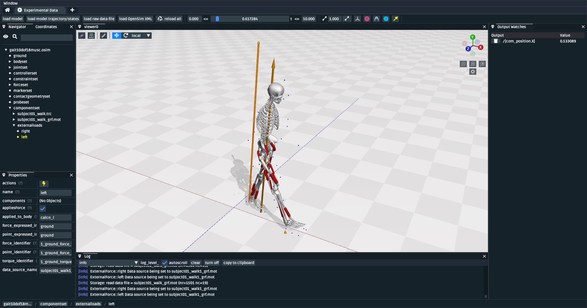
Fig. 7.1 A screenshot of the preview experimental data UI. Here, the subject01.osim
model file from the OpenSim Models Repository is loaded, which shows
the model file; additionally, the subject01_walk.trc (markers, blue spheres) and
subject01_walk_grf.mot (ground-reaction forces, orange arrows) are
overlaid as raw data files. The model’s trajectory (subject01_walk_IK.mot),
as calculated from OpenSim’s inverse kinematic (IK) solver, was loaded against
the model, showing it’s computed motion. This is useful for verifying that
the various experimental data files, and solver results, make sense when combined.#
7.1. Prerequisites#
This is a standalone tutorial. The preview experimental data workflow is a standalone UI for handling experimental data. You don’t necessarily need to know how to build or handle an OpenSim model in order to use it effectively, but those skills are useful for debugging a model-specific issue.
For your own work, you will need to have your experimental data files in a format that’s compatible with OpenSim (e.g.
trc,sto). Typically, this requires either using an OpenSim-aware data exporter, or writing a script that converts your experimental data from your source format into an OpenSim-compatible format. The data formats used by OpenSim are typically simple plaintext formats, which means that you can generally (e.g.) use a one-off python script to generate them. We recommend looking at some existing OpenSim-compatible data files (e.g. this Example MOT File from the OpenSim Models Repository) for inspiration.
7.2. Topics Covered by this Tutorial#
A high-level overview of the preview experimental data workflow UI.
A concrete walkthrough of using the preview experimental data UI in a typical experimental workflow.
7.3. Opening the Preview Experimental Data UI#
The preview experimental data UI is an independent “workflow” UI that can be
accessed from OpenSim Creator’s splash screen, in the Workflows section:
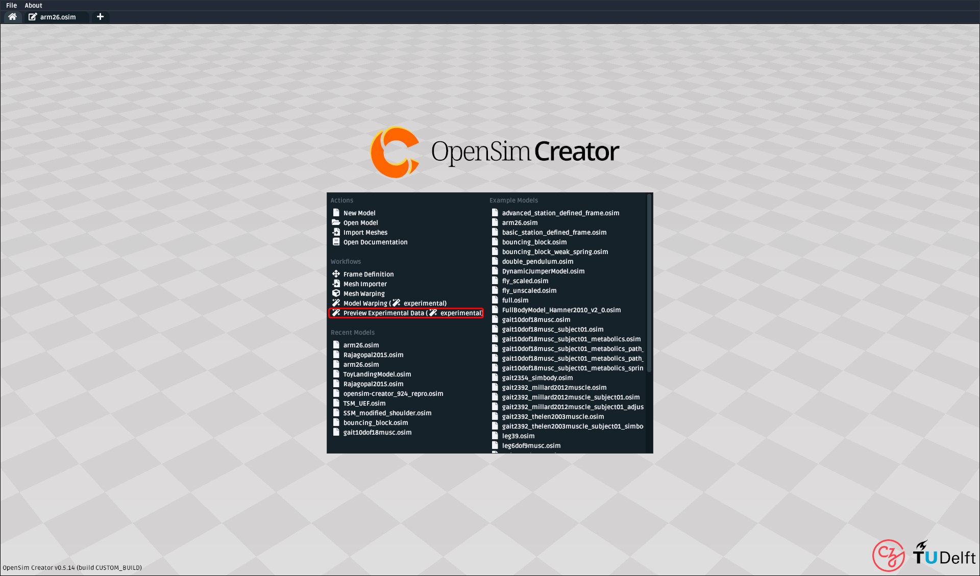
Fig. 7.2 How to open the preview experimental data UI from the splash screen. It’s
also accessible from the File menu.#
7.4. Preview Experimental Data UI Overview#

Fig. 7.3 The preview experimental data UI. In its current (🪄 experimental) iteration,
it has buttons for loading a model, the model’s associated trajectory, raw
data files (unassociated to the model), and OpenSim XML files (e.g. ExternalLoads).#
The preview experimental data UI provides similar panels to the model editor
UI (e.g. Coordinates, Navigator), but with some key differences that
are tailored towards visualizing and debugging experimental data:
It can load a model trajectory. The
load model trajectorybutton in the top toolbar lets you load a trajectory (e.g.sto) against the current. This is useful for (e.g.) debugging whether the output from OpenSim’s Inverse Kinematics (IK) solver matches your experimental data.It can load raw experimental data files. The
load raw data filebutton in the top toolbar lets you load raw data files into the scene. The data series in the raw data file can then be clicked, inspected, scrubbed, etc. to visualize how OpenSim understands them. Because they are “raw” data files they are unconnected to any frame in the model and always display in ground.It can load associated OpenSim XML files. The
load OpenSim XMLbutton in the top toolbar reads any<OpenSimDocument>and puts it in the model’scomponentset, which associates it with the model. This is useful for (e.g.) associating anExternalLoadsto a model which, when force-vector visualization is enabled in a 3D viewer, lets you view when/where those forces are applied to the model.It has a time scrubber. There’s a time scrubber (slider) in the top toolbar, which lets you set/modify the currently-viewed time. This doesn’t involve any kind of solver or simulation (e.g. forward-dynamics). It only sets the current model’s time, so that (e.g.) any associated motions, raw data, or
ExternalLoadsreflect their impact at that point in time. This is useful for ensuring data behaves as-expected over time.It can reload all of the above with a single click. The
reload allbutton in the top toolbar is designed to reload everything in one click and scrub to the currently-scrubbed-to time. This is useful for debugging/fixing/editing the external files in an external editor, followed by reloading.
In combination, these features let you set up a single workplace where you can work on/with experimental data to solve your research problems. The next section describes, concretely, how they interplay in an example workflow.
7.5. Walkthrough: Markers to Motion#
In this section, we will go through a typical workflow that uses the preview experimental data UI.
This walkthrough makes more sense if we use a little bit of 🧙♂️ roleplay to
explain each step’s context. Imagine that you’ve already recorded some experimental
data and have made/acquired subject01.osim. You are now at the stage in your
project where problems like loading/validating raw data and linking it to the
OpenSim model are bottlenecks.
7.5.1. Download Raw Data and Models#
Note
🧙♂️ Roleplay: you painstakingly collected this data from the lab, probably.
In this section, we will be using experimental data from the OpenSim Models Repository.
Specifically, the Gait10dof18musc’s OutputReference data (Gait10dof18musc Model Direct Link).
Download the data: download a stripped-down zip of
Pipelines/Gait10dof18musc/OutputReferencefrom this link and unzip it somewhere.Any filepaths in this tutorial are relative to the data folder. E.g. if something in this tutorial says “load
ExperimentalData/subject_walk.trcthen that path is relative to the folder that you unzipped.
7.5.2. Load Raw Marker Data#
Note
🧙♂️ Roleplay: you want to check the marker data before using it with OpenSim’s IK solver. Does it have reasonable locations, reasonable motion, and correct labels?
The first step is to load the raw marker data (.trc) file into the UI. To do
that, you will need to:
Click the
load raw data filebutton in the toolbarSelect the
subject01_walk.trcfile (path:ExperimentalData/subject01_walk.trc).
Once loaded, it should look something like this:
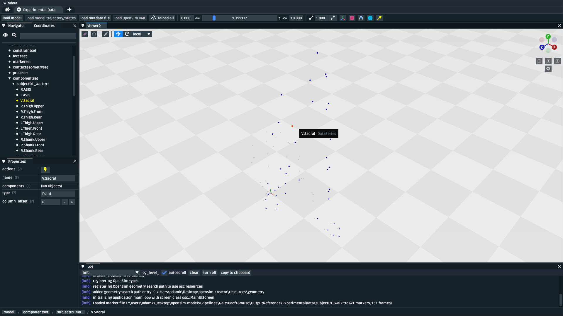
Fig. 7.4 The preview experimental data UI after loading subject01_walk.trc. The
UI shows the marker locations as blue spheres. The time range for scrubbing
can be adjusted using the min/max boxes either side of the scrubbing slider.#
With the markers loaded, you can now:
Inspect whether they match your expectations. The top toolbar lets you scrub to different times in raw data, which helps with visualizing the motion of the model.
Double-check marker labels. You can hover/click the markers to see their name, or view the names in the
Navigatorpanel. This can be handy for double-checking that the marker data was labelled correctly. The OpenSim IK solver generally assumes that the data labels match the names ofOpenSim::Markers in your model.Edit the .trc file. If there’s any problems, you can edit the underlying
.trcfile using a text editor (e.g. Visual Studio Code, Notepad++) and then clickReload Allin the Preview Experimental Data UI to reload the data. This is useful for tweaking labels, reversing axes, etc.
7.5.3. Load IK Result#
Note
🧙♂️ Roleplay: you were satisfied with the marker data and used it with OpenSim’s IK solver in a process described here. You now want to inspect the IK result.
After confirming that the marker data looks reasonable, you can then use it with your model and OpenSim’s IK solver to yield a trajectory. You can overlay the model + trajectory in the preview experimental data UI with the following steps:
Load the model: Click
load modeland choosesubject01.osim, which, in this example, was the model that was used with the IK solver.Load the trajectory: Click
load trajectory/statesand chooseIK/subject01_walk_IK.mot, which, in this example, is the result from OpenSim’s IK solver.
Once loaded, you should be able to see the raw marker data, your model, and its motion all overlaid:
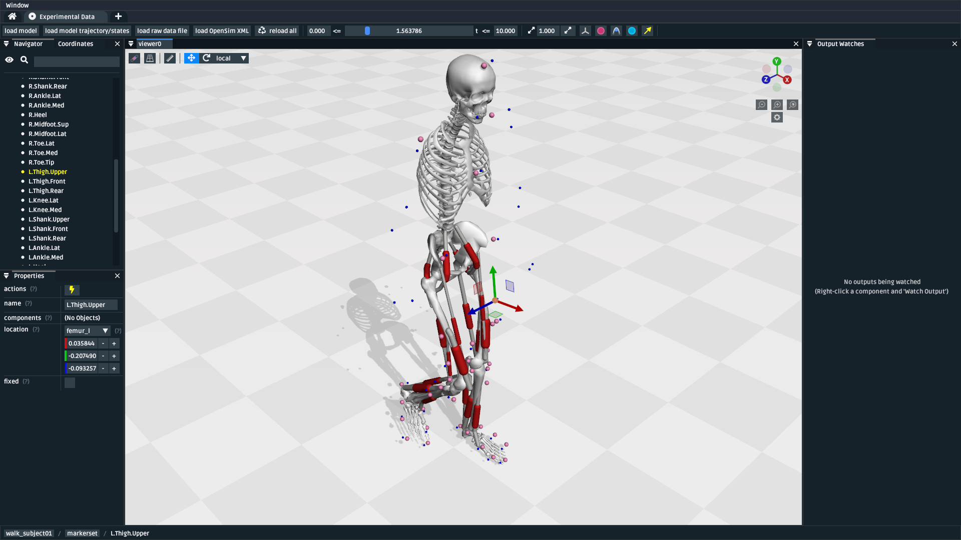
Fig. 7.5 The preview experimental data UI after loading the raw marker data, the model, and the IK result. This is useful for visually inspecting how closely the model trajectory from IK matches the input marker locations.#
7.5.4. Load Raw Ground Reaction Forces#
Note
🧙♂️ Roleplay: your experiment also recorded ground reaction forces (GRFs) on a force plate. You want to make sure that the GRFs are synchronized with the rest of the data and point in the right direction.
This step is identical to Load Raw Marker Data :
Click the
load raw data filebutton in the toolbarSelect the GRF data,
subject01_walk_grf.mot(path:ExperimentalData/subject01_walk_grf.mot).
Once loaded, you should be able to see the marker data, your model, the model’s motion, and your GRF vectors overlaid:
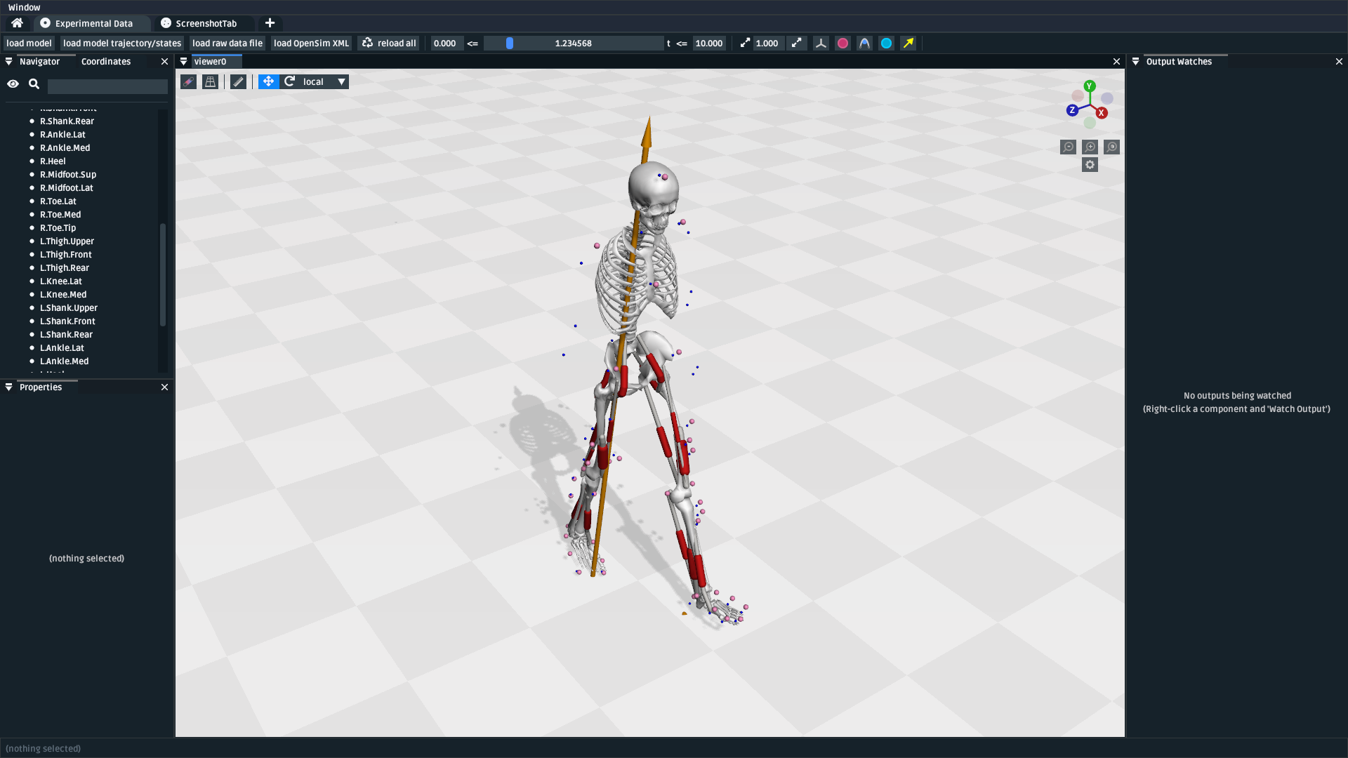
Fig. 7.6 The preview experimental data UI after loading the marker data, model, IK trajectory, and GRFs. The UI shows the GRFs are orange arrows.#
Similarly to Load Raw Marker Data, you can edit the underlying GRF file to fix any issues, such as vectors pointing in the wrong direction or invalid column headers.
7.5.5. Learn about ExternalLoads (optional)#
Note
🧙♂️ Roleplay: you want to use the GRFs with OpenSim’s Inverse Dynamics
(ID) solver. However, OpenSim requires either an ExternalLoads XML file
to link the GRFs to the model. You want to know what that means.
OpenSim’s tools don’t usually use raw experimental data directly. Instead, they
tend accept a description of how the raw data should be combined with the model.
ExternalLoads is one such description. However, writing an ExternalLoads file
is a common source of errors. This section aims to demystify what’s going on.
- Experimental Motivation
Imagine you’ve attached an accelerometer to a subject’s hand. If you load its measurements into the UI with
load raw data file, then the UI will show the measurements with respect to the origin (ground). This represents what the accelerometer recorded.However, you know where that sensor was attached (the hand). So you know where those raw measurements should be expressed–and applied to–in your model.
ExternalLoadsis how you “explain” that relationship to OpenSim.
It’s a good idea to carefully read through and understand an example ExternalLoads
file. Although your use-case is likely to be different from this walkthrough’s,
all ExternalLoads files ultimately contain the same fields. Here is a
slightly stripped-down version of subject01_walk_grf.xml, used later in
the next part of this walkthrough:
 1<?xml version="1.0" encoding="UTF-8" ?>
 2<OpenSimDocument Version="30000">
 3  <ExternalLoads name="WalkingGRF">
 4    <objects>
 5      <ExternalForce name="left">
 6    <!--Flag indicating whether the force is disabled or not. Disabled means that the force is not active in subsequent dynamics realizations.-->
 7    <isDisabled>false</isDisabled>
 8    <!--Name of the body the force is applied to.-->
 9    <applied_to_body>calcn_l</applied_to_body>
10    <!--Name of the body the force is expressed in (default is ground).-->
11    <force_expressed_in_body>ground</force_expressed_in_body>
12    <!--Name of the body the point is expressed in (default is ground).-->
13    <point_expressed_in_body>ground</point_expressed_in_body>
14    <!--Identifier (string) to locate the force to be applied in the data source.-->
15    <force_identifier>1_ground_force_v</force_identifier>
16    <!--Identifier (string) to locate the point to be applied in the data source.-->
17    <point_identifier>1_ground_force_p</point_identifier>
18    <!--Identifier (string) to locate the torque to be applied in the data source.-->
19    <torque_identifier>1_ground_torque_</torque_identifier>
20    <!--Name of the data source (Storage) that will supply the force data.-->
21    <data_source_name>Unassigned</data_source_name>
22      </ExternalForce>
23
24      <!-- further <ExternalForce> blocks can be added here-->
25
26    </objects>
27    <groups />
28    <!--Storage file (.sto) containing (3) components of force and/or torque and point of application.Note: this file overrides the data source specified by the individual external forces if specified.-->
29    <datafile>subject01_walk_grf.mot</datafile>
30  </ExternalLoads>
31</OpenSimDocument>
The comments (<!-- comment -->) explain the role of each field. The most
common problems that tend to be encountered are:
The
datafileis incorrect. It should name the associated raw data file. Paths are relative to where theExternalLoadsfile is saved.The
_identifierfields don’t match the headers indatafile. Internally, OpenSim uses the_identifiers in a prefix search throughdatafile’s columns. For example, if you specifypoint_identifierasmy_force_pthen OpenSim is going to searchdatafilefor 3 adjacent columns namedmy_force_px,my_force_py,my_force_pz.The data is in the wrong coordinate system (left-handed, rather than right-handed), or the wrong units. This is visualized via the preview experimental data UI, which tries to draw the resulting force vectors on the model (explained later). You may need to use external software/scripts to make your data suitable for use in an
ExternalLoads.
The key takeaways from this (optional) explanation section are to understand
what ExternalLoads does and how to modify it for your purposes. If it still
seems unclear, we suggest going through the Pipelines/ section of the OpenSim Models Repository
and looking at how previous researchers wrote the files.
7.5.6. Associate an ExternalLoads to the Model#
Note
🧙♂️ Roleplay: you’ve written an ExternalLoads file for your GRFs and
now you want to verify that it’s correct before (e.g.) using it with OpenSim’s
Inverse Dynamics (ID) solver.
An ExternalLoads XML file can be associated to a model that’s loaded in the
preview experimental data UI. Concretely, with the example data, you can do
that with the following steps:
Load the ExternalLoads’ XML: Click
load OpenSim XMLin the toolbar and opensubject01_walk_grf.xml(path:ExperimentalData/subject01_walk_grf.xml).Enable 3D Body / Point Force Visualization: In the top-left of any 3D viewer panel, there’s a grid icon for toggling visual aids. Enabling either
Forces on Bodies,Torques on Bodies, orPoint Forcesshould draw theExternalForce’s force vectors.
Once loaded, you should be able to see the marker data, your model, the model’s
motion, your raw GRF vectors, and the ExternalForces from the ExternalLoads
file overlaid:
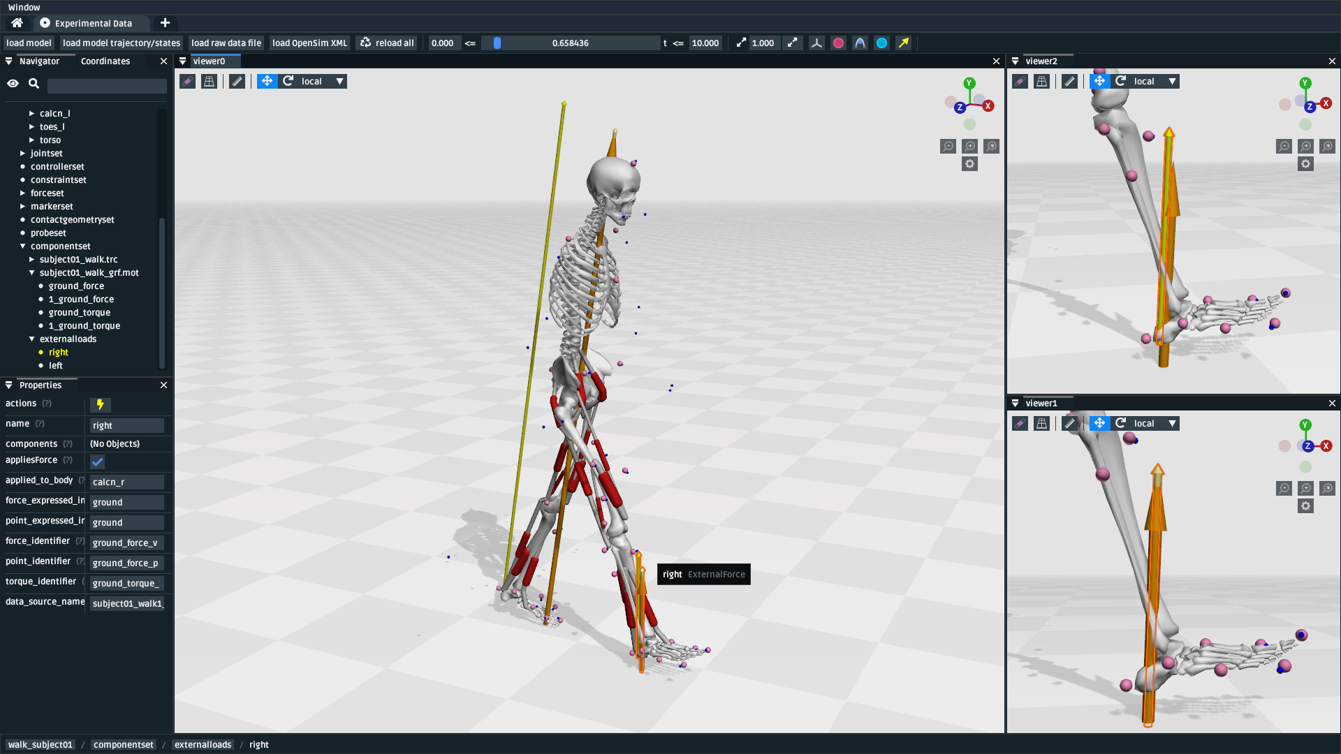
Fig. 7.7 The preview experimental data UI after loading the marker data, model, IK
trajectory, raw GRFs, and ExternalLoads. Dark-orange arrows are raw GRF
measurements, light-yellow arrows are the forces applied via the ExternalLoads. Here, three 3D viewer panels
were opened with different visual aids: Left: muscles, body forces, and
point forces. Top-Right: body forces. Bottom-Right: point forces.#
Because the point forces are well-aligned with the raw GRF data, it’s likely
that the ExternalLoads file applies the forces in the correct coordinate
system. Visualizing the body force vectors shows which bodies are ultimately
receiving the forces.
A key benefit of the preview experimental data UI is that the raw data files,
model, and trajectory can be loaded separately into a single 3D scene on a
single timeline, which makes debugging synchronization and spatial issues easier.
Another benefit is that the UI keeps track of which files were opened, so that
the Reload All button is capable of reloading everything from scratch. This
means that you can (e.g.) edit the ExternalLoads file in an external editor
followed by reloading the scene in the UI in order to fix any data issues.
7.6. Summary#
In this tutorial, we covered (typical use-cases of) the preview experimental data UI. This is useful when trying to connect experimental data to OpenSim models. We hope to add more functionality to the UI over time.
More generally, this tutorial also outlines a general philosophy for handling experimental data. This is because it’s challenging. The general philosophies we are trying to encourage are:
Work Incrementally: handle each data file, or configuration file, one-at-a-time. Handle any errors as you go along. Otherwise, debugging will be much more complicated.
Don’t Fly Blind: always aim to have some kind of visual feedback when going through each step. Confirm that the something’s there and that it looks reasonable.
Be Deliberate: Don’t just (e.g.) copy and paste an
ExternalLoadsfile from the internet, or use a wizard, because it’s required by a solver in the OpenSim GUI. Figure out why it’s necessary and what it’s doing. Read through the file - they don’t bite, much 🧛♀️.
If you follow those steps, we believe you’ll find it easier to integrate experimental data with OpenSim models.
7.7. (Optional) Extra Exercises#
Play with previous models that have experimental data. The OpenSim Models Repository contains a collection of OpenSim models and examples of how those models were used with experimental data (in
Pipelines/). It’s an excellent source for seeing how previous researchers have combined OpenSim with experimental data to do something useful. One of the pipelines from that repositoryGait10dof18muscwas used to write the walkthrough section of this tutorial. SimTK.org is also a good source for published OpenSim models.