
2. Make a Bouncing Block#
In this tutorial, we will be making a bouncing block using OpenSim Creator:
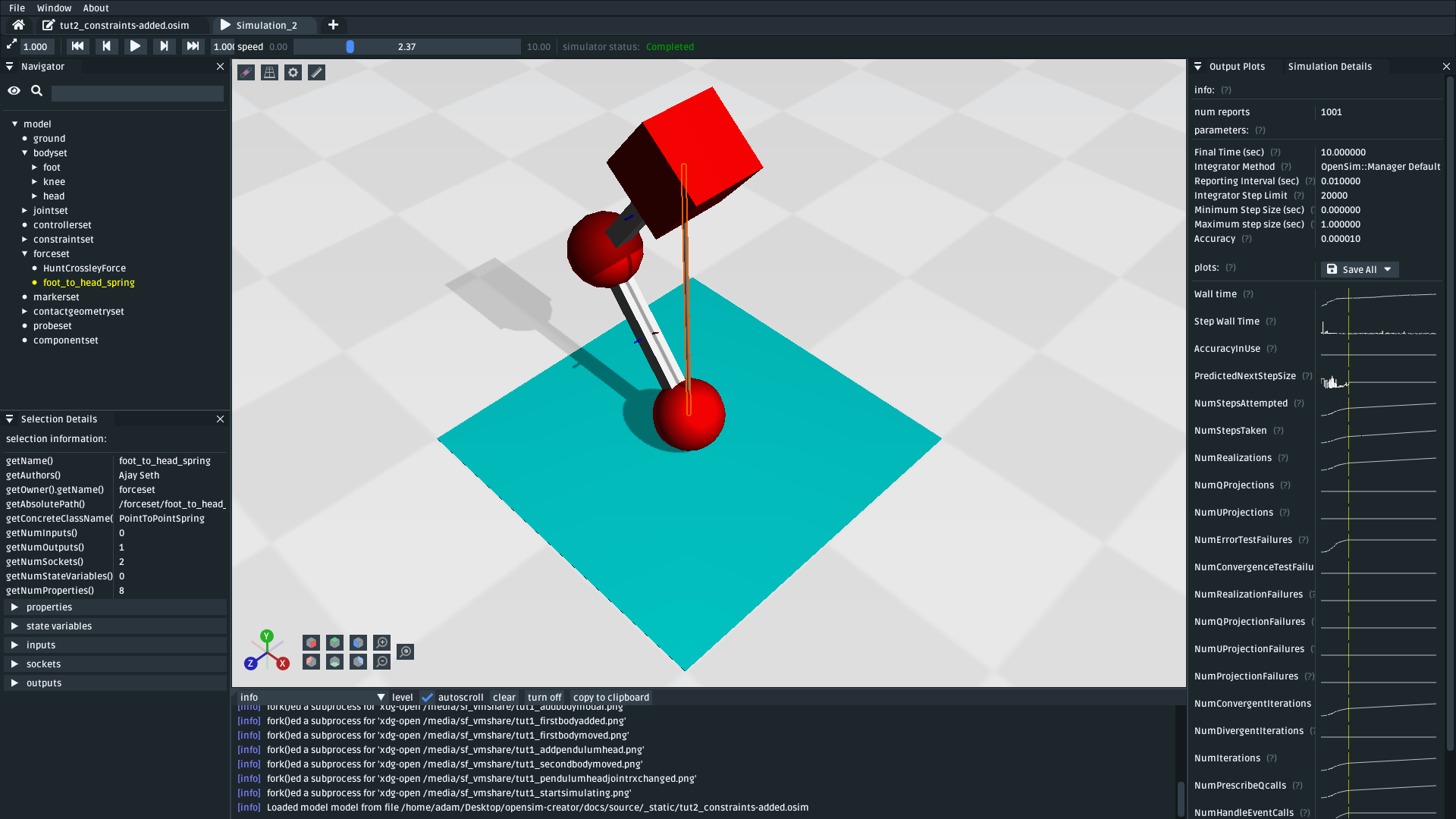
Fig. 2.1 The model that’s made in this tutorial. It is a three-body system with a spring attached between the head to the foot. Contact geometries are used to make the model bounce on the floor, and constraints are used to prevent it from rolling around (download model).#
In Make a Pendulum, we created a pendulum: one of the most basic physical systems that can be modelled. This tutorial reinforces concepts from that tutorial by building a slightly more complex model that contains collisions, forces, and constraints. This tutorial builds the model incrementally (i.e. from the ground up), so that we can explore each model-making decision one step at a time.
2.1. Prerequisites#
This tutorial assumes that you have already completed Make a Pendulum. Because of that, the content here will skip over some steps.
If you feel lost at any point, there should be partial solutions available along the way. Keep an eye out for the download model links.
2.2. Topics Covered by this Tutorial#
Creating a slightly more advanced (than Make a Pendulum) model that also contains collisions, forces, and constraints.
Editing the collision surfaces/forces (orientations, radii, etc.).
How forces are used in OpenSim models. An example of how they can be used.
Why constraints are sometimes necessary in OpenSim models.
2.3. Create the Foot#
Because of how OpenSim computes a model’s spatial layout, the most straightforward way to develop a new OpenSim model is to start at whichever body will be directly attached to ground (e.g. foot) followed by adding bodies that are, in turn, attached to that (e.g. knee).
Starting from the “middle” (e.g. knee), or a “leaf”, of a model’s topology graph is more challenging because the position and orientation of those entities may change when they are attached to bodies that are (topographically) closer to ground.
Note
The body that is attached to ground does not need to be the body that is spatially closest to ground in the model. It just needs to be whichever body you think should be positioned relative to ground. In this tutorial, we are starting at the foot, which happens to also be the body that’s closest to the ground. Conversely, OpenSim Creator contains an example model, bouncing_block.osim, which is similar to the model we will build here, but built from the head towards the foot.
The reason that this tutorial builds this model from the foot upwards is so that we can experiment with collisions earlier in the tutorial. If we built the model from the head, we would have to wait until the knee, foot, and foot_collision were added before we could experiment with collisions.
The first thing we need to add to our model is the foot body. As explained in Make a Pendulum, all bodies (which are frames) need to be attached to other frames in the model and, ultimately, attached to ground. In our model, the foot will be an (initially) freely-moving element in the scene, so we will directly attach it to the ground with a FreeJoint.
Using similar steps to what was taught in Make a Pendulum:
Create a new model.
Add a body called
footinto the model. It should have a mass of1 kg(the default) and be joined togroundwith aFreeJointcalledground_to_foot. Attach aSpheregeometry to it.Click the sphere in the 3D viewport and use the properties panel to change its
Appearanceproperty to a red color.
You can then raise foot above the ground slightly by altering the ground_to_foot joint’s ty coordinate:
Use the navigator panel to select the
ground_to_footjoint within the model’sjointsetExpand
ground_to_footin the navigator panel and select thetycoordinateUse the properties panel to change
ty’sdefault_valueproperty from0.0to0.5
This should produce a model with a red sphere (foot) that is raised above the ground:
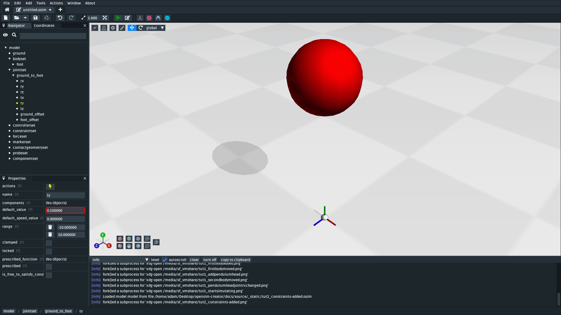
Fig. 2.2 The model after adding the foot body and changing ground_to_foot’s ty to 0.5 (download model)#
Note
Why do we change the ty coordinate, rather than changing (e.g.) the translation property of foot_offset?
In Make a Pendulum we moved bodies around by altering the translation property of offset frames. Here, we are changing the ty coordinate. This exploits the fact that FreeJoint s have alterable translation coordinates.
Both of these approaches for moving bodies around in the model have equivalent side-effects. However, coordinates have the added benefit of being user-editable. The official OpenSim GUI contains a coordinates panel that lets users easily change coordinates. This enables users to (e.g.) later change ty to make the model start higher off the ground.
2.4. Add Contact Surfaces & Forces#
If you simulate the model at this point, foot will just fall through the floor. The reason this happens is because the chequered floor and red sphere geometry are only decorative: the foot body is effectively a 0D point in space that has nothing to collide with.
In order to give foot a “size” that can “collide” with stuff, we need to explicitly add ContactGeometry into the model at locations where we logically expect collisions to take place. In this case, we will add ContactGeometry at the same location as the decorations.
To attach a collidable floor (a ContactHalfSpace) to the ground of the model:
Open the
Addmenu from the main menu, or by right-clicking an empty part of the 3D sceneOpen the
Contact Geometrysub-menu and clickContactHalfSpaceIn the popup, create a
ContactHalfSpacewith the following properties:
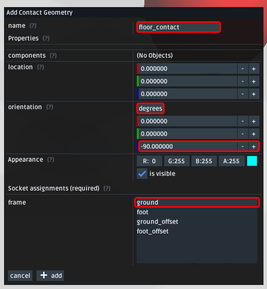
Fig. 2.3 Properties for the floor_contact component (a ContactHalfSpace) attached to the ground. Careful that orientation is set to -90 (degrees) in Z. +90 would behave differently, because a ContactHalfSpace only collides on one side.#
To attach a collidable sphere (a ContactSphere) to foot:
Open the
Addmenu from the main menu, or by right-clicking an empty part of the 3D sceneOpen the
Contact Geometrysub-menu and clickContactSphereIn the popup, create a
ContactSpherewith the following properties:
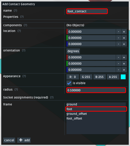
Fig. 2.4 Properties for the foot_contact component (a ContactSphere). The radius is set to match the Sphere decoration used on the foot. The ContactSphere is attached to foot so that collisions it encounters affect foot. Note: You can edit the radius property of foot_contact if you can’t see it in the scene. It may be hidden inside the foot sphere (they have the same radius).#
With those two contact geometries added, the model now contains enough contact geometry to model the collisions we are interested in. However, if you try to simulate this model you will find that foot still just falls through the floor 😕. What’s going on?
In OpenSim, contact geometries only express a geometry that may participate in contact (collision) detection. They do not express the force that is generated whenever contact occurs. We need to separately add a suitable contact force (in this case, a HuntCrossleyForce) into the model. The force handles what physically happens to the model (i.e. which forces are applied to model) whenever a collision occurs.
To add a contact force (HuntCrossleyForce) to the model:
Open the
Addmenu from the main menu, or by right-clicking an empty part of the 3D sceneOpen the
Forcesub-menu and clickHuntCrossleyForceIn the popup, just click the
addbutton (don’t edit anything)If it isn’t selected, select the force in the navigator panel (
forceset/HuntCrossleyForce)Open the force’s context menu by right-clicking it in the navigator panel, or click by clicking the lightning (“actions”) icon
Click
Add Contact GeometrybuttonUse that action to add
floor_contactandfoot_contactto the force. They should end up being listed inHuntCrossleyForce’s properties
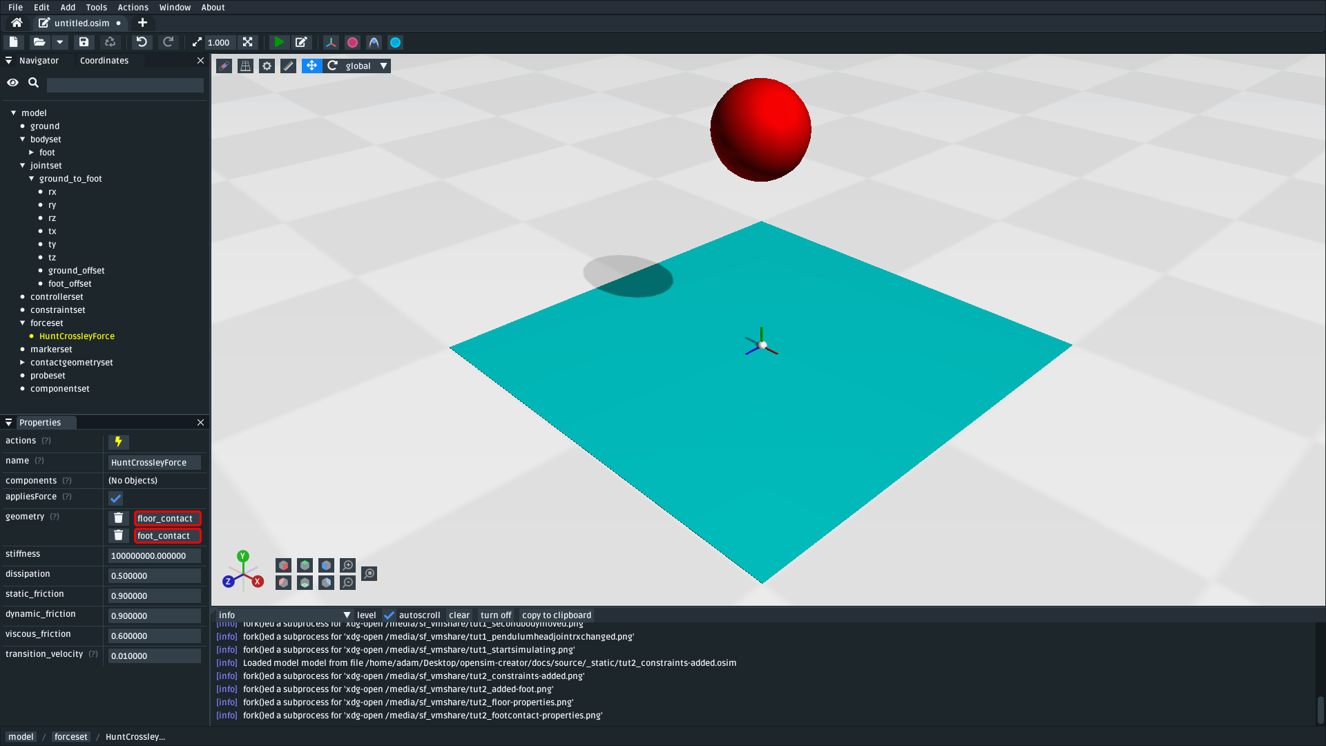
Fig. 2.5 The model after assigning floor_contact and foot_contact to HuntCrossleyForce.#
With the contact force added, simulating this model should show foot hit floor, bounce a little, then stop. You can change the HuntCrossleyForce’s properties to change how stiff the contact force is, how much energy is dissipated by the contact, etc.
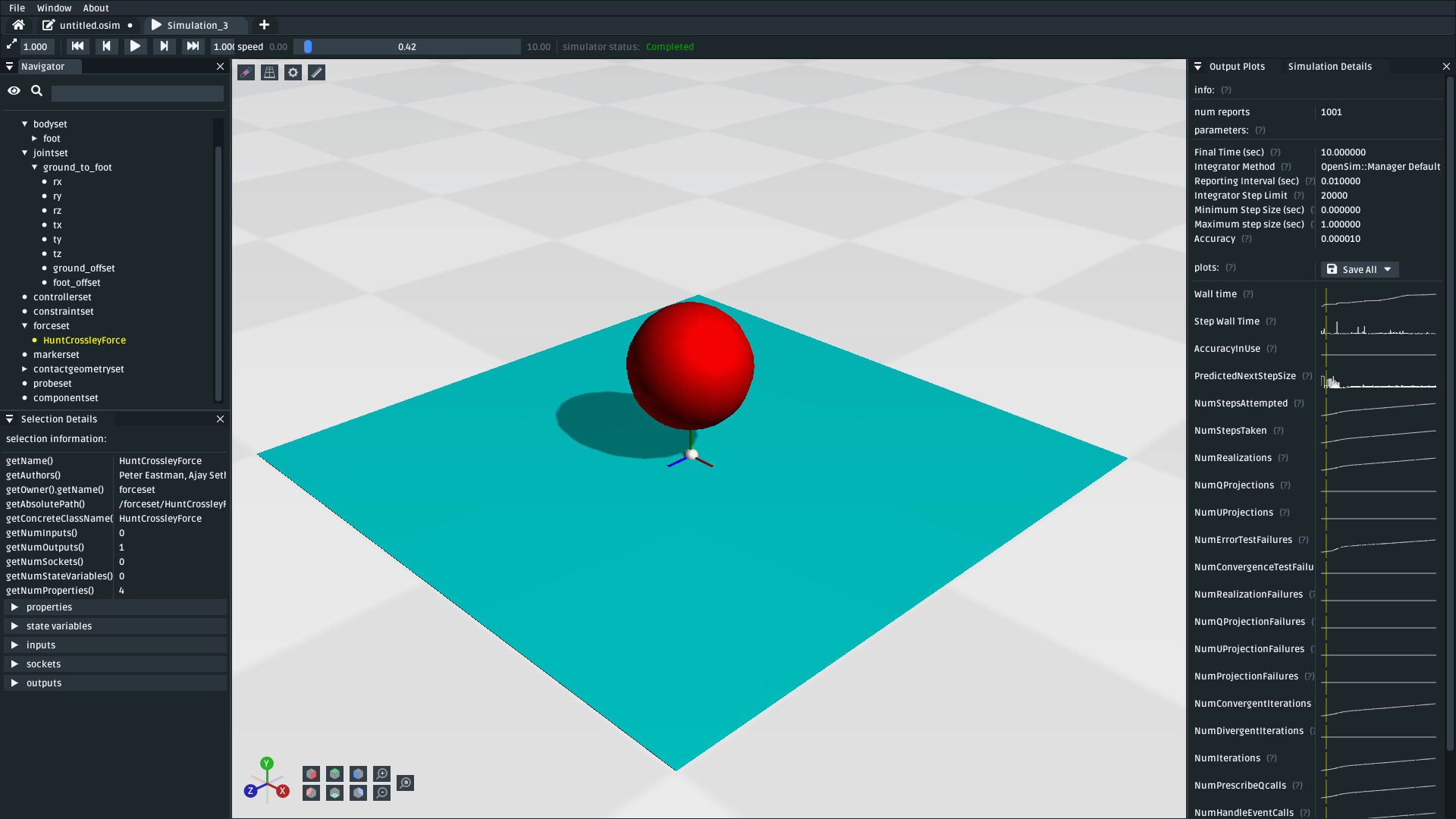
Fig. 2.6 The model after adding floor_contact, foot_contact and a HuntCrossleyForce. Simulating (Ctrl+R) the model should show the foot sphere fall through the scene until it collides with the surface. It should then bounce a little and stop (download model).#
2.5. Attach the Knee & Head to the Foot#
The next step is to add a “knee” and “head” to our foot. This mostly involves the body-addition steps that were previously explained in Make a Pendulum.
To add the knee to the model:
Add a body called
kneeinto the model. It should have a mass of1 kgand be joined tofootwith aPinJointcalledfoot_to_knee. Attach aSpheregeometry to it.Use the properties panel to change the
translationproperty of thefoot_offset(/jointset/foot_to_knee/foot_offset) from(0, 0, 0)to(0, 0.5, 0). This is so that thefootis offset from the origin of thefoot_to_kneeandkneeis co-located with it (i.e. it swings at the knee).Click on the new
knee_geom_1sphere and use the properties panel to change theAppearanceproperty such that the sphere is red.
To add the head to the model:
Add a body called
headinto the model. It should have a mass of1 kgand be joined tokneewith aPinJointcalledknee_to_head. Attach aBrickgeometry to it.Use the properties panel to change the
translationproperty of theknee_offset(/jointset/knee_to_head/knee_offset) from(0, 0, 0)to(0, 0.5, 0). This is so that thekneeis offset from the origin ofknee_to_headandheadis co-located with it (i.e. it swings at the head).Click on the new
head_geom_1cube and use the properties panel to change theAppearanceproperty such that the cube is red
These steps should create all the necessary bodies in the system, but it will look a little bit unusual (the “links” are missing):
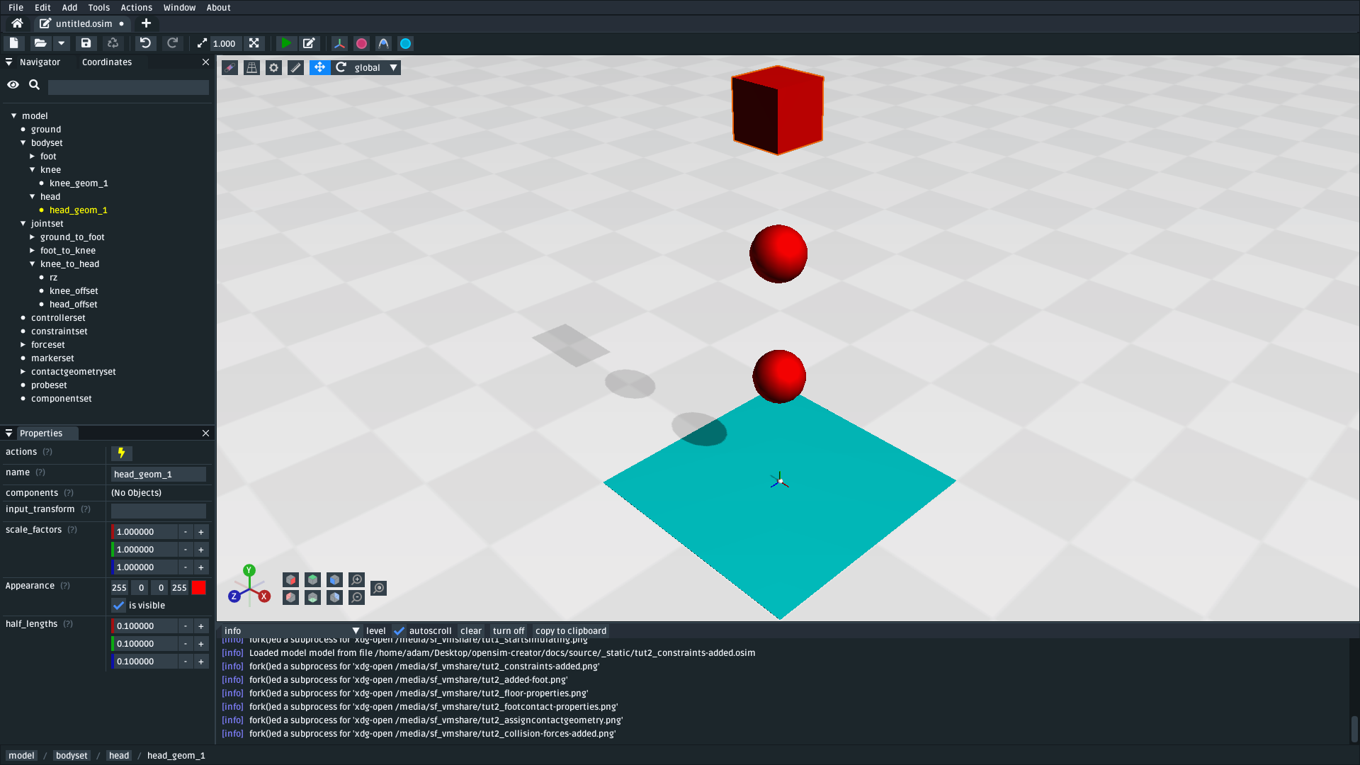
Fig. 2.7 The model after adding the knee and head bodies. The bodies are joined to each over with PinJoint s that pivot on the knee and head respectively. The model looks unusual because there are no visual “links” between the bodies and because the model isn’t angled yet (download model).#
Much like at the end of Make a Pendulum, we can make the model look better by adding extra geometry between the bodies. This can be achieved by attaching decorative geometry to offset frames placed between the blocks.
To add a decorative link between the foot and knee:
Right-click the
footbody (/bodyset/foot) in the navigator panel to open its context menu.Open the
Addmenu and clickOffset FrameSelect the created offset frame (
/bodyset/foot/foot_offsetframe)Use the properties panel to change the offset frame’s
translationproperty to(0.0, 0.25, 0.0). This makes the offset frame sit betweenfootandknee.Right-click the offset frame in the navigator, or click the lightning icon (“Actions”) in the properies panel to open the offset frame’s context menu
Open the
Addmenu and clickGeometry. Attach aBrickgeometry to the offset frameSelect the brick through the navigator (
/bodyset/foot/foot_offsetframe/foot_offsetframe_geom_1), or by clicking it in the 3D viewportUse the properties panel to edit the brick’s
half_widthsproperty to something like(0.025, 0.25, 0.025). This creates a thin “rod” betweenfootandknee

Fig. 2.8 The model after adding the first decorative link. (download model)#
To add a decorative link between the knee and head:
Right-click the
kneebody (/bodyset/knee) in the navigator panel to open its context menuOpen the
Addmenu and clickOffset FrameSelect the created offset frame (
/bodyset/knee/knee_offsetframe)Use the properties panel to change the offset frame’s
translationproperty to(0.0, 0.25, 0.0). This makes the offset frame sit betweenkneeandhead.Right-click the offset frame in the navigator, or click the lightning icon (“Actions”) in the properies panel to open the offset frame’s context menu
Open the
Addmenu and clickGeometry. Attach aBrickgeometry to the offset frameSelect the brick through the navigator (
/bodyset/knee/knee_offsetframe/knee_offsetframe_geom_1), or by clicking it in the 3D viewportUse the properties panel to edit the brick’s
half_widthsproperty to something like(0.025, 0.25, 0.025). This creates a thin “rod” betweenkneeandhead
These steps add decorative features to the model that make it easier to see what’s going on. After doing them, you should have something that looks like this:
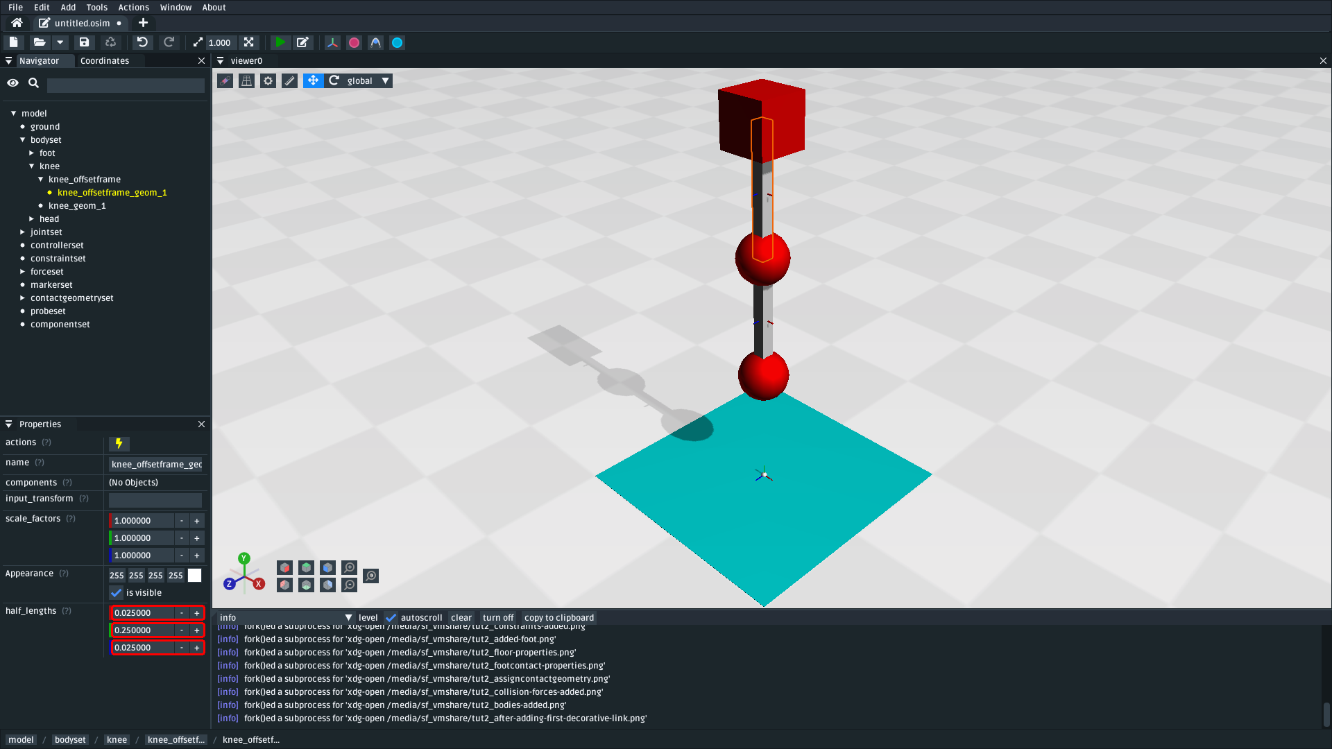
Fig. 2.9 The model after adding decorative bricks between the foot and the knee and between the knee and the head (download model).#
If you try simulating this model, you will find that it falls vertically and remains mostly motionless. The reason why that happens is because all of the bodies in the model (foot, knee, and head) are vertically aligned along Y.
To make the simulation more interesting, we are going to angle the whole model and also change the initial joint angle of foot_to_knee to give the knee a “kink”. To do this:
Angle the whole model by selecting
ground_to_foot’srzcoordinate (/jointset/ground_to_foot/rz). Use the properties panel to change the coordinate’sdefault_valueproperty to0.698.Give the knee a “kink” by selecting
foot_to_knee’srzcoordinate (/jointset/foot_to_knee/rz). Use the properties panel to change the coordinate’sdefault_valueproperty to-1.396.
These steps should put the model into a more interesting arrangement:
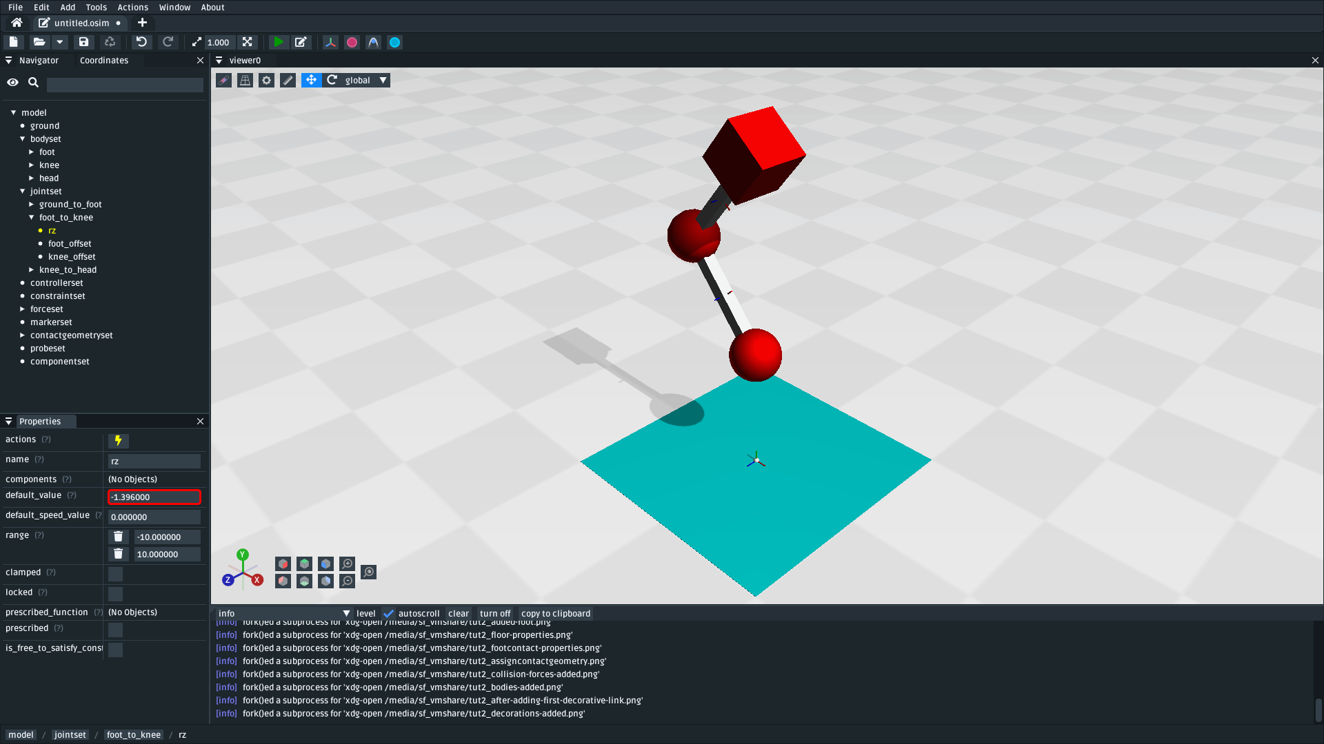
Fig. 2.10 The model after altering the ground_to_foot’s and foot_to_knee’s rz values. Altering those values puts the model into a more interesting arrangement (download model).#
2.6. Add a Spring between foot and head#
We have now added all of the bodies and joints that make up the model. However, the only forces acting on the model are gravity and the foot collision. Consequently, a simulation of the model won’t be very impressive. The model will fall a little, then foot will collide with floor, then the rest of the (non-colliding) model will roll around and clip through the floor.
The reason this model is unexciting is because there are no forces between the model’s bodies. We have attached three bodies (foot, knee, and head) with two PinJoint s and let them drop through space. The joints merely enforce constraints between the bodies. So the model acts like a passive hinged device that flops around.
We can add forces to this model to make it more interesting. Specifically, we will add a PointToPointSpring between the foot and head, which will make the model’s head “bounce” away from the foot whenever it gets too close (e.g. when the model hits the floor).
To add a PointToPointSpring between foot and head:
Open the
Addmenu from the main menu, or by right-clicking an empty part of the 3D sceneOpen the
Forcesub-menu and clickPointToPointSpringIn the popup menu, give the spring the following properties:
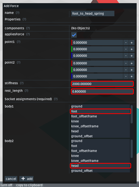
Fig. 2.11 Properties for a PointToPointSpring between the foot and the head in the model. The spring’s stiffness and rest_length properties are chosen to try and make the model equilibrate towards the foot being separated from the head slightly (after a few bounces).#
If you simulate the model after adding the spring, you should see that the model hits the floor, collides, bounces a little bit, and then starts to roll:
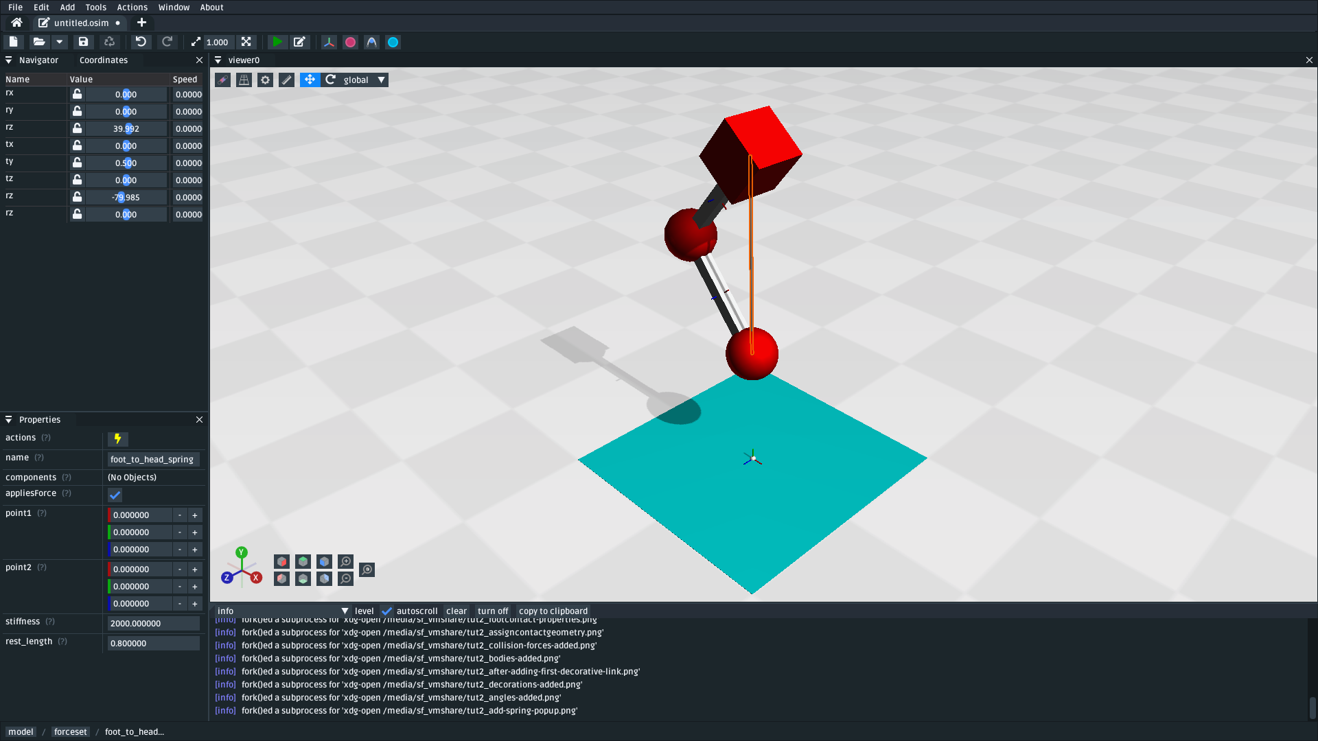
Fig. 2.12 The model after adding a PointToPointSpring between the foot and the head. The spring prevents the head from clipping through the foot and makes the simulation more interesting-looking. However, when simulating, the model bounces around a little bit and begins to roll around. This is because the model isn’t constrained along the vertical axis (download model).#
2.7. Constrain foot and head to stay along Y#
The model is now logically complete–in the sense that it contains all of the mechanical components we want–but it isn’t particularly stable. If you simulate the model, you will find that it bounces a little bit and then starts to roll around on its foot, rather than continuing to bounce up and down.
The reason this happens is because the model isn’t perfectly balanced. It is slightly heavier on knee-side, which causes the whole model to start leaning and, ultimately, roll around. One way to prevent this from happening is to add constraints into the model that prevent it from rolling.
One way to think of constraints is that they are extra “rules” that the model must obey. When the model is assembled and simulated, the simulator has to ensure that each state of the simulation obeys the these constraints. Constraints are commonly used to simplify models in some (acceptable) way.
OpenSim has support for a few different constraints, such as:
Enforcing a constant distance between two frames in the model (
ConstantDistanceConstraint)Enforcing that a frame “follows along” some other frame. E.g. that the frame is only allowed to be some distance along the Y axis of some other frame (
PointOnLineConstraint)Enforcing that two frames must be at the same location and orientation (
WeldConstraint)
For our model, we want to enforce that the foot and head are constrained to always be along the Y axis (i.e. X = 0 && Z = 0). This enforces that both foot and head fall and bounce vertically, which means that the foot_to_head_spring is always bounced straight-on.
To constrain foot to only be allowed to roll along the Y axis, follow these steps:
Open the
Addmenu from the main menu, or by right-clicking an empty part of the 3D sceneOpen the
Constraintsub-menu and clickPointOnLineConstraintIn the popup menu, give the constraint the following properties:
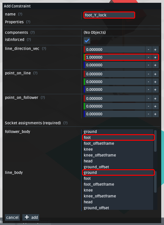
Fig. 2.13 Properties for foot_Y_lock. This constraint prevents the foot from being able to roll along the floor to a different X/Z coordinate in the scene by enforcing foot to follow the (0.0, 1.0, 0.0) line from ground.#
After adding that constraint, you should find that foot no longer rolls around the scene, but head still freely swings around foot as much as it can.
To constrain head, such that is only follows along Y in ground, follow these steps:
Open the
Addmenu from the main menu, or by right-clicking an empty part of the 3D sceneOpen the
Constraintsub-menu and clickPointOnLineConstraintIn the popup menu, give the constraint the following properties:
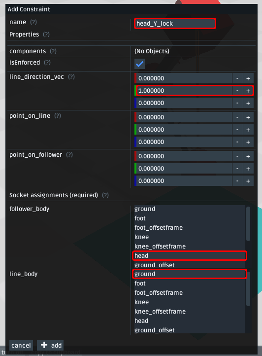
Fig. 2.14 Properties for head_Y_lock. This constraint prevents head from being able to swing around the foot wildly, which ensures that it always bounces towards foot straight-on.#
With both of those constraints in place, the model now bounces up and down without rolling around. This is very useful for figuring out what tuning parameters (e.g. head weight, foot_to_head_spring stiffness) lead to an optimal bounce without having to also handle balancing.
Fig. 2.15 The final model after adding PointOnLineConstraint s that make the head and foot bodies stay along the Y axis, rather than having the freedom to roll around (download model).#
Note
Wait a second, did we just cheat 🤔? A “real” model wouldn’t have these invisible constraints, right?
Yes - technically. But using constraints in this way is a design choice. Design choices are dictated by realities and needs, rather than idealism. Do you need an ideal model, or will a simplified model adequately answer your question?
Take this model as an example. If your main objective is to figure out which angles, masses, and spring strains lead to a perfectly balanced model (e.g. because ideally optimizing the model’s balance is what you need), then you probably don’t want to use constraints because they are interrupting the main objective of your model.
Conversely, if your main objective is to roughly tune the model’s spring and body masses to get the right amount of vertical “bounce”, and you know that the model’s overall balance isn’t relevant (e.g. because you know the device is going to be bounced down a tube or linear rail), then you probably do want to use constraints because they will make it easier to focus on the main objective of your model.
Choosing the right constraints is even more important with complex models. Sure, you could try to perfectly balance a perfectly-modelled human on a perfectly-designed bicycle, and ensure that the various muscle controls etc. keep the bike balanced, but getting that right will probably take a very long time (assuming it’s even possible, given the number of parameters involved). Conversely, you could model a rougher human model on a simpler bicycle model that is constrained to only roll along a 2D plane. That would take significantly less time to model and might be “good enough” to answer your research question.
The art of modelling is in figuring out which simplifications are suitable for your problem. There’s a reason why physicists tend to model everything as a sphere - and frequently get away with it 😉.
2.8. (Optional) Extra Exercises#
Now that you have a working model, you can experiment a little bit by doing these extra exercises.
Experiment with the body masses and spring parameters. What happens if
headis heavier? How does the springstiffnessaffect how the model bounces? Can the floor’s contact forces be modified to reduce how much of the drop force is dissipated each bounce? Can you make it bounce for longer?Try opening your model in the official OpenSim GUI. Save your model to an
.osimand open it in the official OpenSim GUI. This should let you edit coordinates, plot things, etc. The official GUI has features that OpenSim Creator does not have. The benefit of using open file types (.osim) is that you can use multiple tools with your model file.
2.9. Next Steps#
This tutorial was similar to Make a Pendulum, but it introduced some of the more practical parts of designing a model. Things like adding collision geometry, adding forces, and deciding on constraints. These are all important parts of the model-building process that come up repeatably when designing OpenSim models.
As you experienced in this tutorial, a time-consuming step of building an OpenSim model can be initially adding and placing the bodies/joints. The next tutorial, Use the Mesh Importer, introduces an alternative approach for performing these first steps.